
Polymeric bags with pressure relief valves

Active Publication Date: 2006-03-09
REYNOLDS CONSUMER PROD INC
View PDF26 Cites 50 Cited by
  • Summary
  • Abstract
  • Description
  • Claims
  • Application Information

AI Technical Summary

Benefits of technology

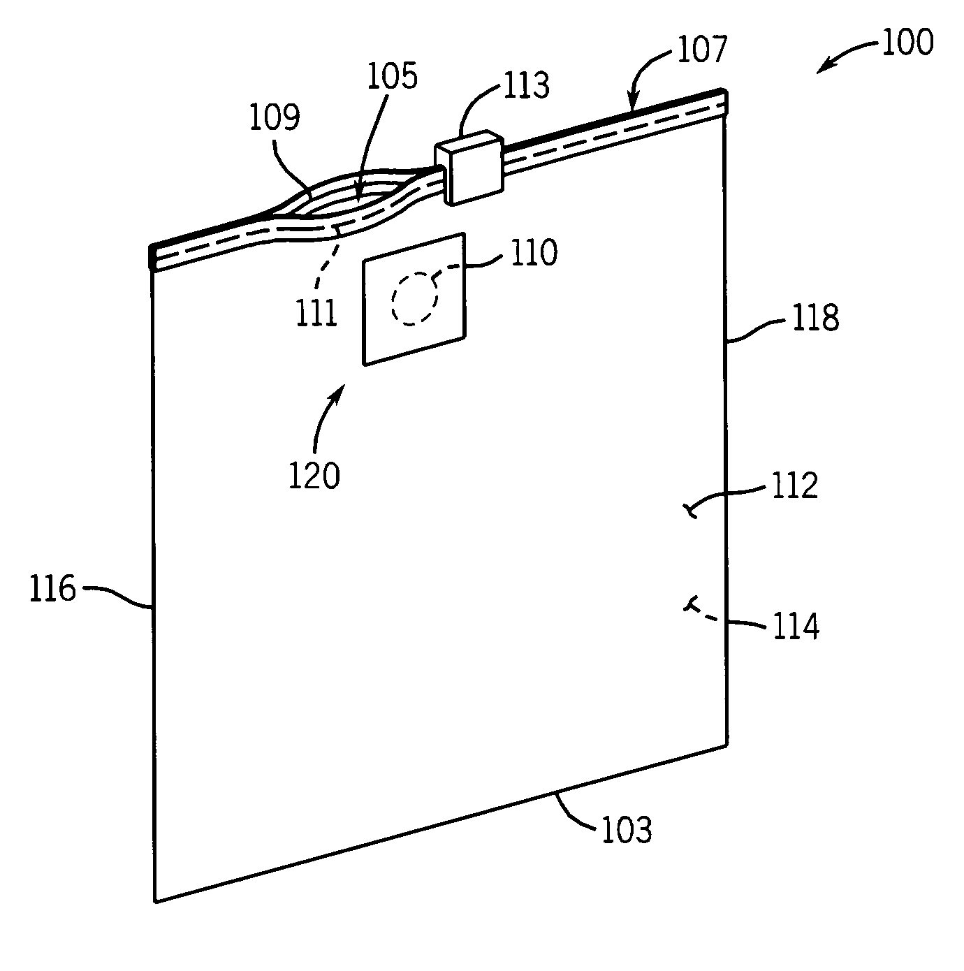
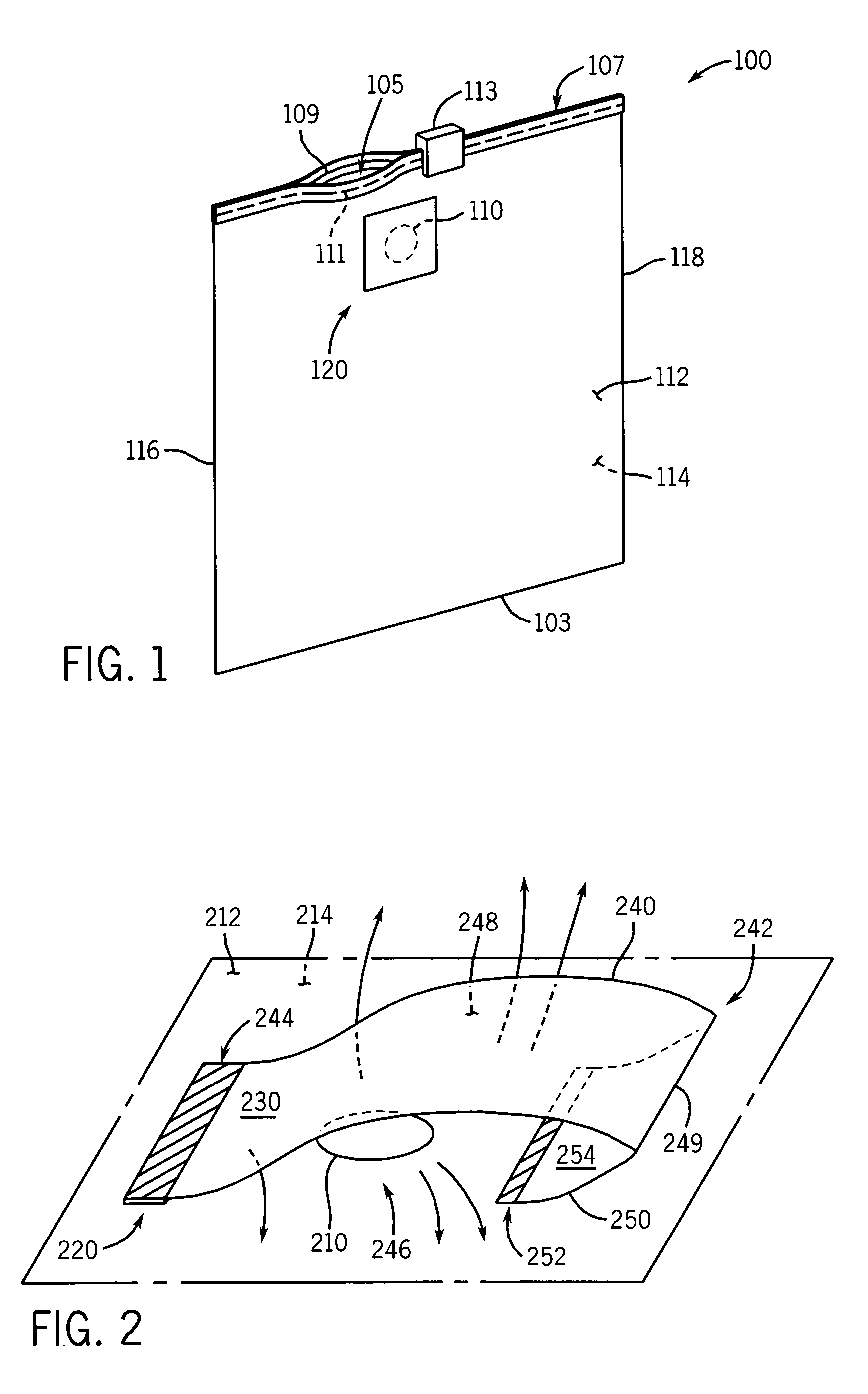
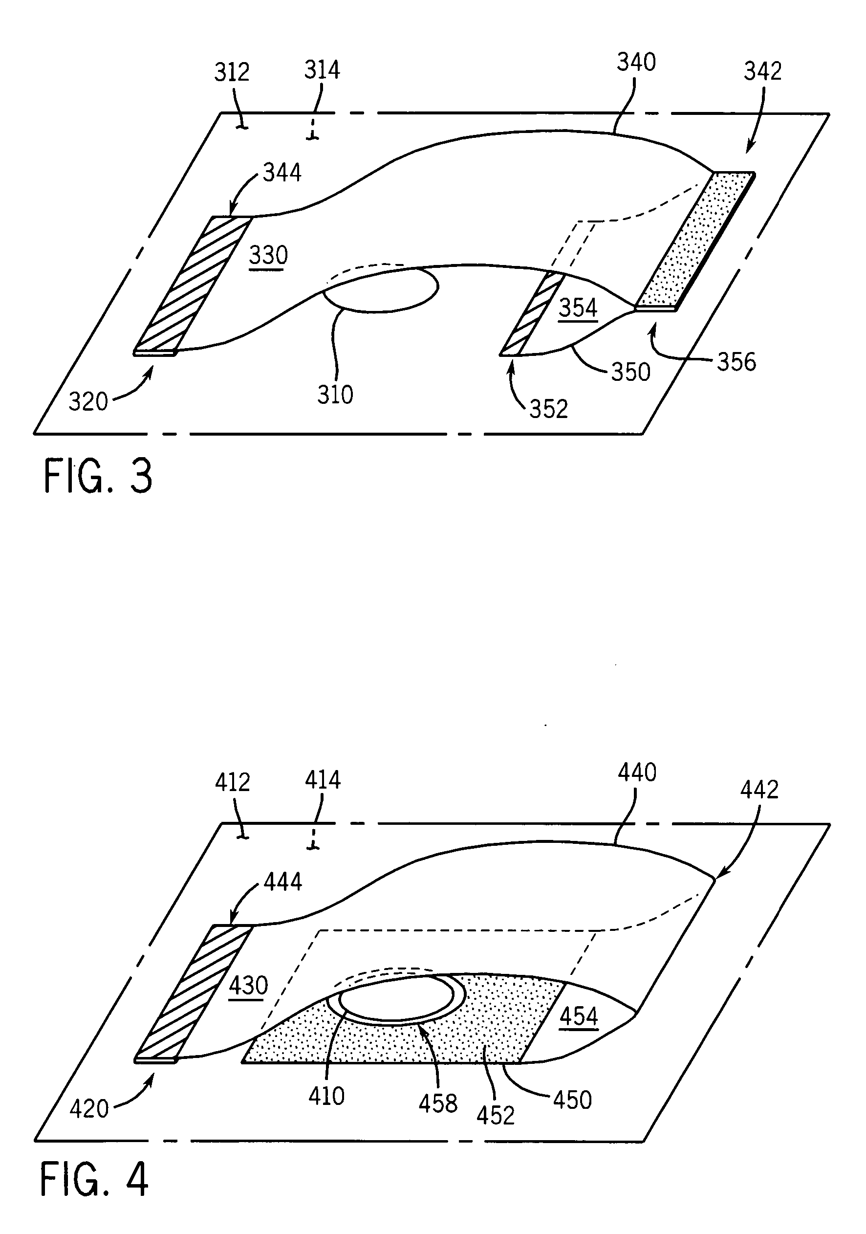
[0010] In accordance with another aspect of the invention, a bag is provided with a pressure relief opening, a pressure relief valve, and a seal line extending proximate the pressure relief opening. Particularly, the seal line at least partially attaches the first and second body panels of the bag together. The seal line extends from or proximate the pressure relief opening to a location beyond the pressure relief valve. In this manner, when pressure is applied to the bag to open the pressure relief valve, a dimple is formed in the panel proximate the pressure relief valve the enhance the flow of air therefrom. In some embodiments, the seal line extends inwards from a corner of the bag formed in the intersection between one of the opposing bag sides and the bottom. Alternatively, the seal line extends inwards from a corner of the bag formed in the intersection between one of the opposing bag sides and the fastener. The angle of the seal line can be substantially 45 degrees with respect to the one of the opposing bag sides.
[0012] During a method of operation of each of the disclosed bags of the present invention, one or more items are placed in a bag, the reclosable fastener of the bag is placed in a closed position, and pressure is applied to the opposing body panels of the bag, causing air and other gases to exit the bag through the pressure relief opening. The pressure exerted by the exiting gases causes the cover member to bend, bulge, flex, or otherwise move away from the body panel, which allows the gases to exit through at least one open side of the pressure relief valve. Once returned to its relaxed state, e.g., upon release of the pressure applied to the opposing body panels, the cover member covers and seals the pressure relief opening, inhibiting or preventing flow of air and other gases into and out of the bag.

Problems solved by technology

After closure, such bags often contain air, which can accelerate the spoilage of the food items stored in the bags.
Many of these valves are complicated to construct and difficult to operate and provide unsatisfactory sealing and venting properties, thereby inhibiting their utility.

Method used


Image

  • Polymeric bags with pressure relief valves
  • Polymeric bags with pressure relief valves
  • Polymeric bags with pressure relief valves

Examples


Embodiment Construction

[0019] Illustrative embodiments will now be described to provide an overall understanding of the disclosed polymeric bags with pressure relief valves. One or more examples of the illustrative embodiments are shown in the drawings. Those of ordinary skill in the art will understand that each disclosed polymeric bag having a pressure relief valve can be adapted and modified to provide alternative embodiments of polymeric bags with pressure relief valves for other applications, and that other additions and modifications can be made to the disclosed polymeric bags with pressure relief valves without departing from the scope of the present disclosure. For example, features of the illustrative embodiments can be combined, separated, interchanged, and / or rearranged to generate other embodiments. Such modifications and variations are intended to be included within the scope of the present disclosure.

[0020] In accordance with the invention, a polymeric bag is provided having opposing body p...


PUM


Abstract

Polymeric bags with pressure relief valves having improved sealing and venting properties are described. Generally, the disclosed bags have opposing body panels connected along a pair of sides, a bottom bridging the sides, reclosable fasteners extending along mouths formed opposite the bottoms, and pressure relief valves attached to one of the body panels. The valves are positioned adjacent a pressure relief opening defined in a body panel of the bag and include a cover member that covers the opening. The cover member includes an upper layer and a lower layer, in which the upper layer is hingedly connected at a first end to the lower layer. The lower layer includes a first portion attached to the body panel and a second contiguous portion not attached to the body panel for relative movement therebetween. The first end of the upper layer is connected to the second portion of the lower layer. Additional aspects include a seal line extending proximate the pressure relief opening to contour a dimple in the bag during operation of the pressure relief valve and surface modifications to enhance sealing of the pressure relief valve when closed.

Description

CROSS-REFERENCE TO RELATED APPLICATIONS [0001] This application claims the benefit of provisional application No. 60 / 605,082 filed Aug. 27, 2004, the entire content of which is expressly incorporated herein by reference thereto.FIELD OF THE INVENTION [0002] The present invention relates to plastic and polymeric bags. More specifically, the present invention relates to pressure relief valves and methods for removing air and other gases contained in such bags. BACKGROUND OF THE INVENTION [0003] A variety of plastic or polymeric bags are well known and used for sundry applications. Generally, a polymeric bag includes first and second opposing body panels that are fixedly attached to each other along a pair of opposing bag sides and a bottom that extends between the pair of bag sides. The body panels, the bag sides, and the bottom define a receptacle space having a mouth formed opposite the bottom. [0004] Many types of polymeric bags include a reclosable fastener extending along the mou...

Claims


Application Information

Patent Timeline
IPC IPC(8): B65D33/16B65D33/01
CPCB65D77/225B65D33/2591B65D33/2508
Inventor BLYTHE, JAMES S.BELIAS, WILIAM P.THOMAS, TOBY R.
Owner REYNOLDS CONSUMER PROD INC
Learn More