Fluid Dynamic-Pressure Bearing Device and Spindle Motor

a technology of dynamic pressure bearing and bearing device, which is applied in the direction of sliding contact bearings, mechanical equipment, mechanical energy handling, etc., can solve the problems of increasing shaft loss, preventing sufficient reduction of shaft loss, and large losses of thrust dynamic pressure bearings, so as to facilitate the maintenance of oil amount and reduce the height of the bearing devi

Active Publication Date: 2006-03-09
NIDEC CORP
View PDF8 Cites 75 Cited by
  • Summary
  • Abstract
  • Description
  • Claims
  • Application Information

AI Technical Summary

Benefits of technology

[0011] According to the present invention, the interface of lubricating liquid is placed on the side surface of the bearing and the bearing gap and the interface are communicated with each other through an annular gap. With this configuration, the annular gap portion also serves as an oil buffer, thus easily maintaining the amount of oil. Further, this configuration is widened in the radial direction of the bearing, thus enabling reduction of the height of the bearing device.

Problems solved by technology

In a conventional fluid dynamic-dynamic bearing device, the thrust dynamic-pressure bearing has been formed at such an annular gap portion, and thus it has been positioned radially outside of the bearing, thus causing an increase of the shaft loss.
Particularly, in the case of a compact-size bearing, such losses in the thrust dynamic-pressure bearing are relatively large.
However, even in such a case, an annular gap is left, thus preventing sufficient reduction of the shaft loss.
If air bubbles are accumulated within the annular gap portion, this may cause troubles such as leakage of the lubricating liquid since the lubricating oil is pushed out due to the thermal expansion of air bubbles.

Method used


Image

  • Fluid Dynamic-Pressure Bearing Device and Spindle Motor
  • Fluid Dynamic-Pressure Bearing Device and Spindle Motor
  • Fluid Dynamic-Pressure Bearing Device and Spindle Motor

Examples


first embodiment

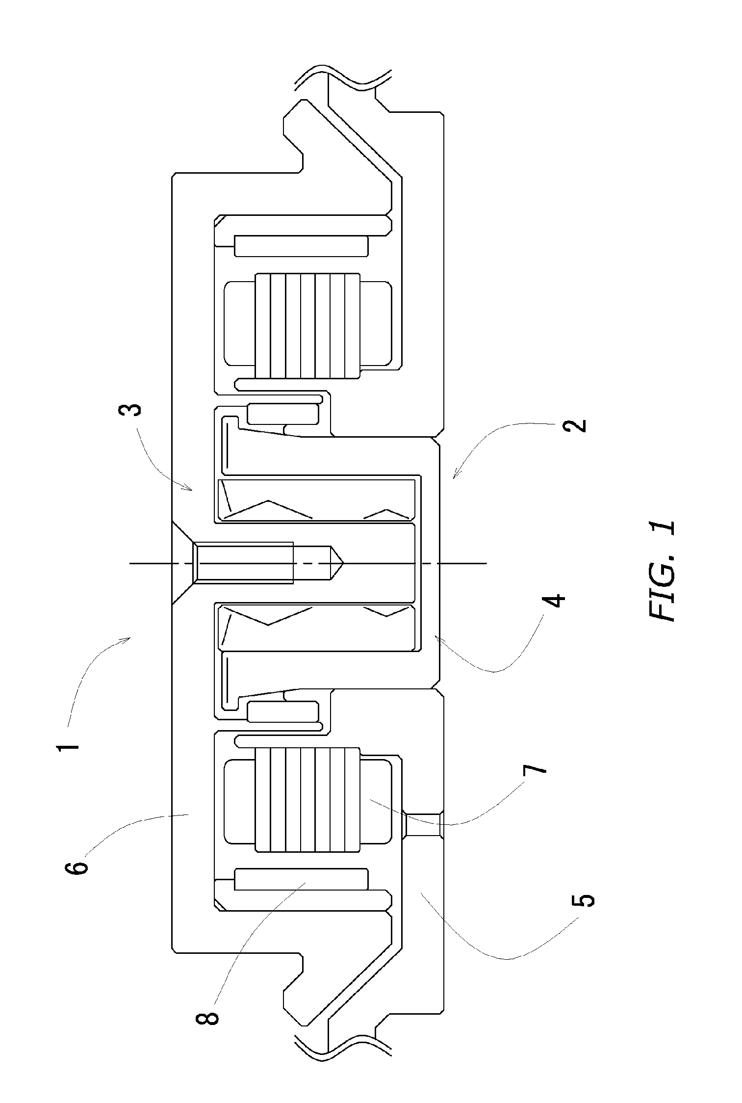
[0046]FIG. 1 is a cross-sectional view of a spindle motor 1 according to the present embodiment. The spindle motor 1 incorporates a fluid dynamic-pressure bearing device 2 according to the present embodiment and a rotor 6 is supported by the fluid dynamic-pressure bearing device 2 such that it is rotatable with respect to a fixed portion 4.

[0047] The fixed portion 4 is constituted by a base plate and a stator 7 secured thereon and the fluid dynamic-pressure bearing device 2 is also installed on the fixed portion at the center portion thereof. The outer periphery of the stator is faced with a rotor magnet 8 mounted on the rotor 6 in the radial direction and, when the stator is energized with a proper phase, the rotor magnet 8 is subjected to a rotational driving force centered on the bearing device, thus causing the rotor to rotate.

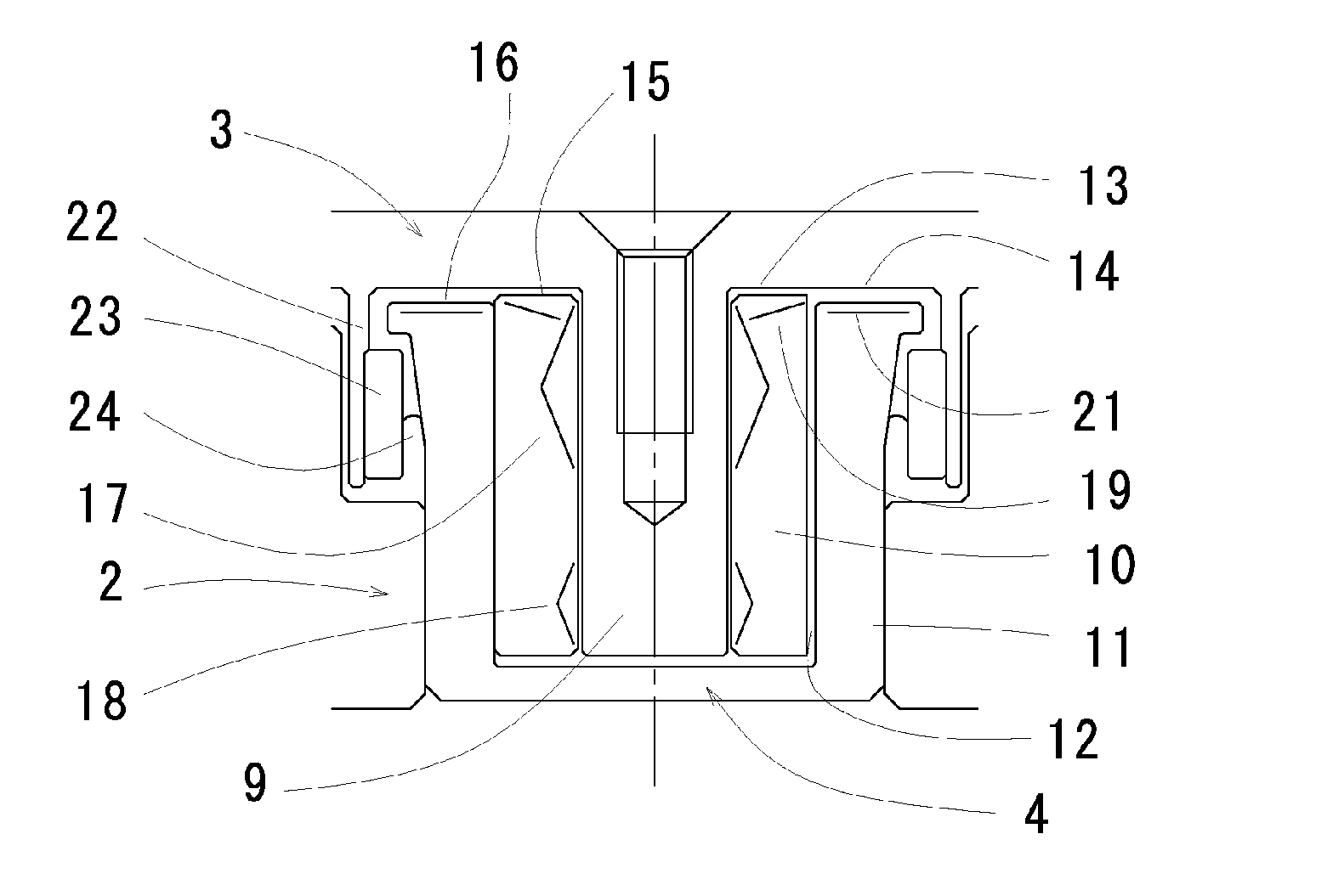
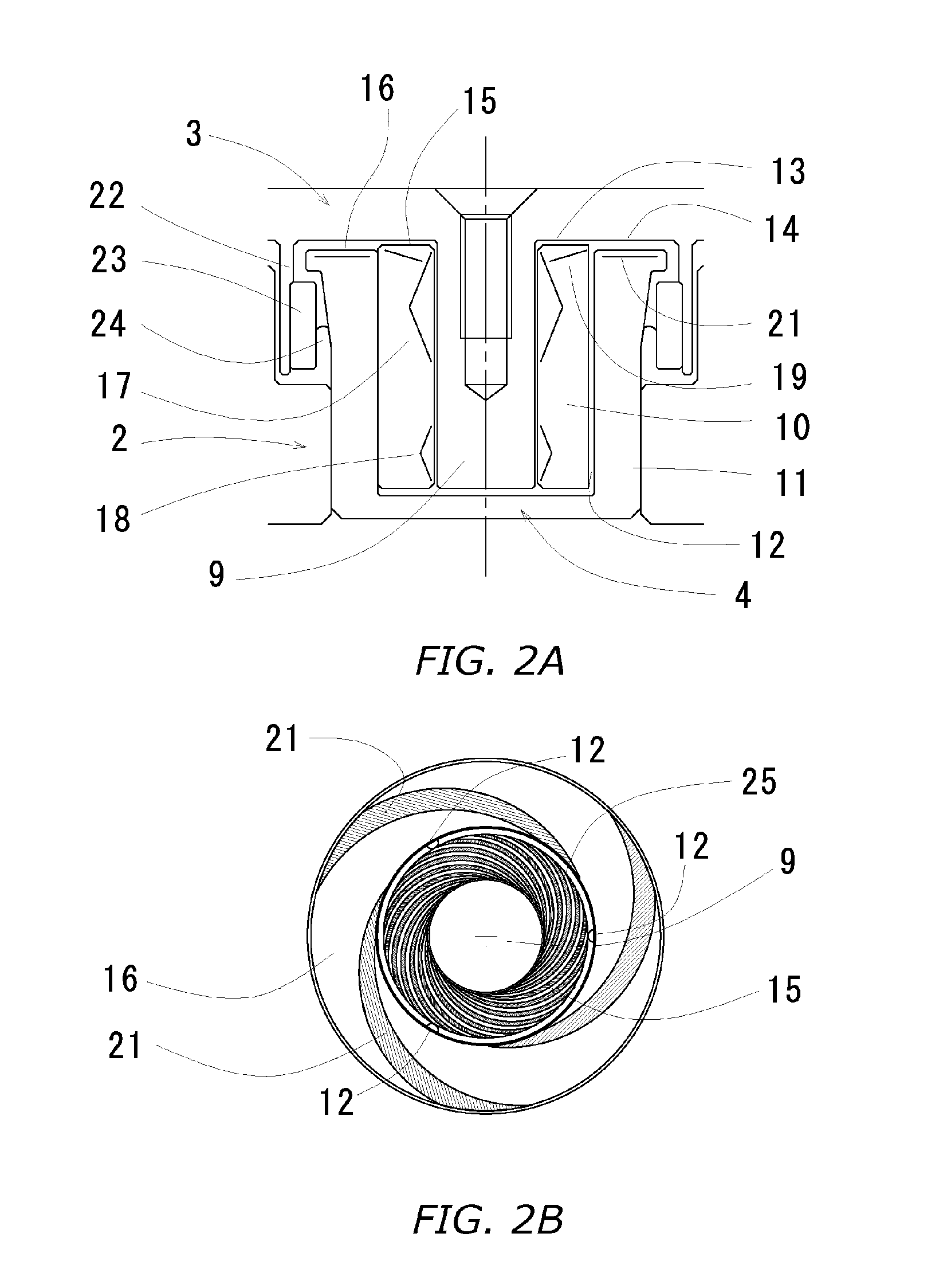
[0048]FIG. 2 are views illustrating detail portions of the fluid dynamic-pressure bearing device 2 and FIG. 2A is a cross-sectional view and FIG. 2B is ...

second embodiment

[0062]FIG. 6 illustrates a modified embodiment which is provided by making a partial modification to the fluid dynamic-pressure bearing device according to the first embodiment. FIG. 6B illustrates the portion encircled by the dot line in FIG. 6A in an enlarged manner.

[0063] In the fluid dynamic-pressure bearing device, the flange surface 16 is inclined outwardly in the radial direction of the bearing. Thus, the dimension of the annular gap is g2 near the inner periphery of the flange surface 16, while it is g3 which is greater than g2 near the outer periphery thereof. Further, the distance w1 between the outer periphery of the flange surface and the inner peripheral surface of the cylindrical peripheral surface 22 is equal to or greater than g3, and the width w2 of the sealing gap 27 at the base portion thereof is set to be equal to or greater than w1.

[0064] With this configuration, radial shear flows within the lubricating liquid are gradually decreased with increasing distance ...

third embodiment

[0067]FIG. 7 illustrates another embodiment 1 of the fluid dynamic-pressure bearing device including a thrust plate 35 provided at the shaft tip end. This fluid dynamic-pressure bearing device 2b includes two thrust dynamic-pressure bearings 19 and 20 which generate opposite supporting forces. The annular gap 33 is placed outside of the upper thrust dynamic-pressure bearing 19 and communicates the sealing gap 24 with the bearing gap.

[0068] The thrust dynamic-pressure bearings 19 and 20 are both configured to gradually increase the pressure of the lubricating liquid towards the radial bearings. The pair of the dynamic-pressure bearings are placed at the upper and lower portions such that they generate opposite supporting forces. These thrust dynamic-pressure bearings generate dynamic pressures thus generating supporting forces in the thrust direction and also increase the pressure within the radial narrow gap 30. The lubricating liquid comes into contact with atmosphere within the s...


PUM


Abstract

Small-size, small-height fluid dynamic-pressure bearing device that causes a low shaft loss and is less prone to troubles such as shortage and leakage of lubricating liquid. A thrust dynamic-pressure bearing is formed at an inner position and a region having a slightly-widened gap is provided outside of the thrust dynamic-pressure bearing to retain the lubricating liquid therein. Further, an oil circulating path is communicated with the region having a slightly widened gap. The gap of this region is set to be greater than the gap at the thrust dynamic-pressure bearing portion by the value of the depth of dynamic-pressure generating grooves. The region having a widened gap may be provided with rows of grooves for stirring-up lubricating oil towards the center.

Description

BACKGROUND OF THE INVENTION [0001] 1. Field of the Invention [0002] The present invention relates to fluid dynamic-pressure bearing devices for use in hard disk driving devices and hard disk devices incorporating the fluid dynamic-pressure bearing device for rotatably supporting the disk mounting portion. [0003] 2. Description of the Related Art [0004] In recent years, miniaturization of personal computers and mounting of hard disks into compact-size portable apparatuses have been advanced. Furthermore, miniaturization of hard disks has been also advanced from a conventional size of 3.5 inch size to more miniaturized sizes such as 2.5 inch and 1.0 inch or less. In view of such trends, there has been a need for miniaturization of fluid dynamic-pressure bearing devices for supporting the hub of a hard disk. [0005]FIG. 11 illustrates a fluid dynamic-pressure bearing which places the hub lower surface on the upper surface of a sleeve such that they are faced to each other with a narrow ...

Claims


Application Information

Patent Timeline
Patent Type & Authority Applications(United States)
IPC IPC(8): F16C32/06
CPCF16C17/107F16C33/107H02K7/085F16C2370/12F16C17/045F16C41/008F16C33/745
Inventor NISHIMURA, HIDEKIOKU, YOSHITO
Owner NIDEC CORP
Why Eureka
Try Eureka