Image forming apparatus mounted with replaceable unit, image forming system, and method of controlling image forming apparatus
Inactive Publication Date: 2006-03-09
FUJIFILM BUSINESS INNOVATION CORP
View PDF7 Cites 38 Cited by
Summary
Abstract
Description
Claims
Application Information
AI Technical Summary
This helps you quickly interpret patents by identifying the three key elements:
Problems solved by technology
Method used
Benefits of technology
[0028] According to the present invention, a user can use a replaceable unit other than a genuine article, by the user's intention, even when the replaceable unit other than a genuine article is mounted. Further, according to the present invention, when a replaceable unit has been replaced, it is possible to reduce bad effects caused by a state before the replaceable unit has been replaced.
[0029] Furt
Problems solved by technology
Meanwhile, if a replaceable unit replaced by a user is not a genuine article for an image forming apparatus, there are problems in that the performance of the image forming a
Method used
Image
Click on the blue label to locate the original text in one second.
Reading with bidirectional positioning of images and text.
Examples
first embodiment
[0062] Hereinafter, embodiments of the present invention will be described with reference to the accompanying drawings.
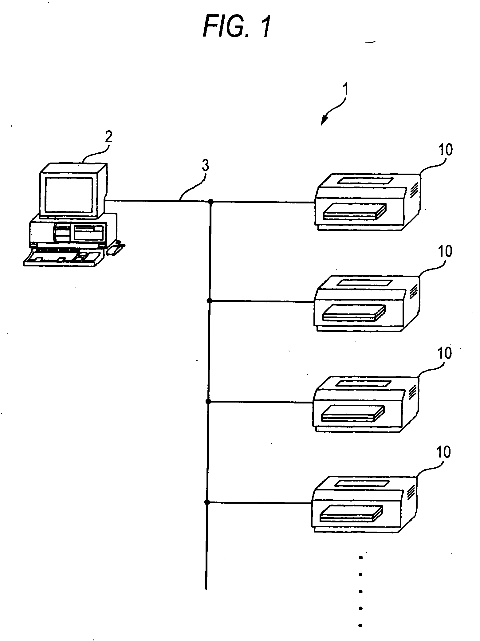
[0063]FIG. 1 illustrates an image forming system 1 according to an embodiment of the present invention. The image forming system 1 is constructed by connecting a host apparatus 2, such as a personal computer (PC) to, for example, a plurality of image forming apparatuses 10 via a network 3. The host apparatus 2 may be a terminal having a control device, such as a micro controller unit (MCU), an input-output device, such as a touch panel, and a communication device for transmitting or receiving signals via the network 3, except the PC. The network 3 may be constructed by wire or wireless. Further, a plurality of the host apparatuses 2 may be connected to the network 3.
[0064] As such, the image forming system 1 is constructed such that the host apparatus 2 can control the image forming apparatuses 10 via the network 3.
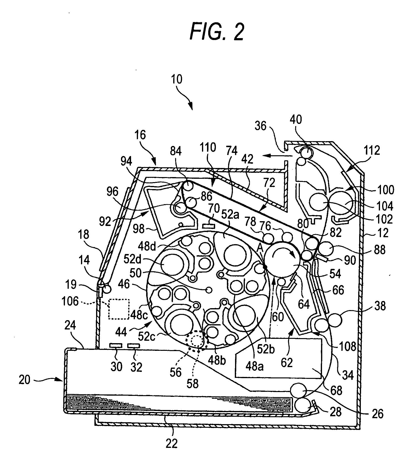
[0065]FIG. 2 schematically illustrates an image ...
second embodiment
[0192] An image forming apparatus, an image forming system, and a method of controlling the image forming apparatus of the second embodiment includes configurations of the first embodiment that are explained by FIGS. 1 to 21. Therefore, in this embodiment, explanations of the overlapped configurations are omitted.
[0193]FIG. 22 is a schematic view illustrating a cross-section of the developer container of the image forming apparatus according to the embodiment of this embodiment.
[0194]FIG. 23 is a memory map exemplifying data stored in a program ROM, a main body NVM and a unit NVM.
[0195] The lifetime threshold values include a theoretical lifetime value of the genuine unit (a first reference value) and a lifetime limit of the genuine unit (a second reference value). The theoretical lifetime value indicates an accumulating usable quantity (for example, an accumulation of the drive time, a multiple value of the pixel, and a number of the print, etc.) when used the genuine unit in an...
PUM
Abstract
When a CPU receives an input signal that selects an operation mode through an operation mode selecting screen, the CPU determines whether or not the selected operation mode coincides with an operation mode stored in individual operation mode histories of an main body NVM. If both the operation modes do not coincide with each other, the CPU starts counting of a midway consumption of a toner representing the consumption of the toner used thereafter. Further, the CPU determines whether or not the count of the midway consumption arrives at a specified value. If the count arrives at the specified value, the CPU updates the individual operation mode histories of the main body NVM with the selected operation mode, and switches an existing operation mode to the selected operation mode.
Description
BACKGROUND OF THE INVENTION [0001] 1. Field of the Invention [0002] The present invention relates to an image forming apparatus mounted with replaceable units, an image forming system, and a method of controlling the image forming apparatus, and more specifically, to an image forming apparatus in which the replaceable units are replaceably mounted in an image forming apparatus main body. [0003] 2. Background Art [0004] An image forming apparatus which allows a user to easily replace a unit including consumables and the like is known. [0005] Meanwhile, if a replaceable unit replaced by a user is not a genuine article for an image forming apparatus, there are problems in that the performance of the image forming apparatus cannot be sufficiently exhibited, like deterioration of the image quality, the operation of the apparatus cannot be guaranteed, or the apparatus can get out of order. This is because the image forming apparatus controls processes for forming an image in consideration...
Claims
Application Information
Patent Timeline
Application Date:The date an application was filed.
Publication Date:The date a patent or application was officially published.
First Publication Date:The earliest publication date of a patent with the same application number.
Issue Date:Publication date of the patent grant document.
PCT Entry Date:The Entry date of PCT National Phase.
Estimated Expiry Date:The statutory expiry date of a patent right according to the Patent Law, and it is the longest term of protection that the patent right can achieve without the termination of the patent right due to other reasons(Term extension factor has been taken into account ).
Invalid Date:Actual expiry date is based on effective date or publication date of legal transaction data of invalid patent.