Handheld extruder welding device

a welding device and extruder technology, applied in the direction of manufacturing tools, ceramic shaping apparatus, coatings, etc., can solve the problems of insufficient robustness of the design for a long-term use, and achieve the effect of preventing excessive heating of the plastic welding wire to be fed into the housing, simple engineering and manufacturing aspects, and easy handling

Inactive Publication Date: 2006-03-09
LEISTER TECHNOLOGIES
View PDF5 Cites 22 Cited by
  • Summary
  • Abstract
  • Description
  • Claims
  • Application Information

AI Technical Summary

Benefits of technology

[0006] According to the invention, the handheld extruder welding device has a housing including several parts. On the screw side, it has a cooling body with air inlets; this body serves as the central mechanical support base that holds the housing walls, the drive system, the screw cylinder, and the hot air unit. Because of its arrangement in the handheld extruder welding device, the cooling body represents a central base component that supports the remaining housing components and absorbs the torsion forces produced by the extruder screw. For this purpose, the cooling body is engineered to be sufficiently stable, is usually made of metal—preferably aluminum—and is joined with the housing, the gear unit, and the screw cylinder in such fashion that it is capable of transmitting the axial and radial forces between the drive system and the screw cylinder. Placing the cooling body on the side of the housing that faces the extruder screw has the advantage that excessive heating of the plastic welding wire to be fed into the housing is thereby prevented, and that the cooling of the gear unit can be accomplished with measures that are simple in terms of engineering and manufacturing aspe

Problems solved by technology

Although it is possible to produce all these handheld extruder welding devices inexpens

Method used


Image

  • Handheld extruder welding device
  • Handheld extruder welding device
  • Handheld extruder welding device

Examples


Embodiment Construction

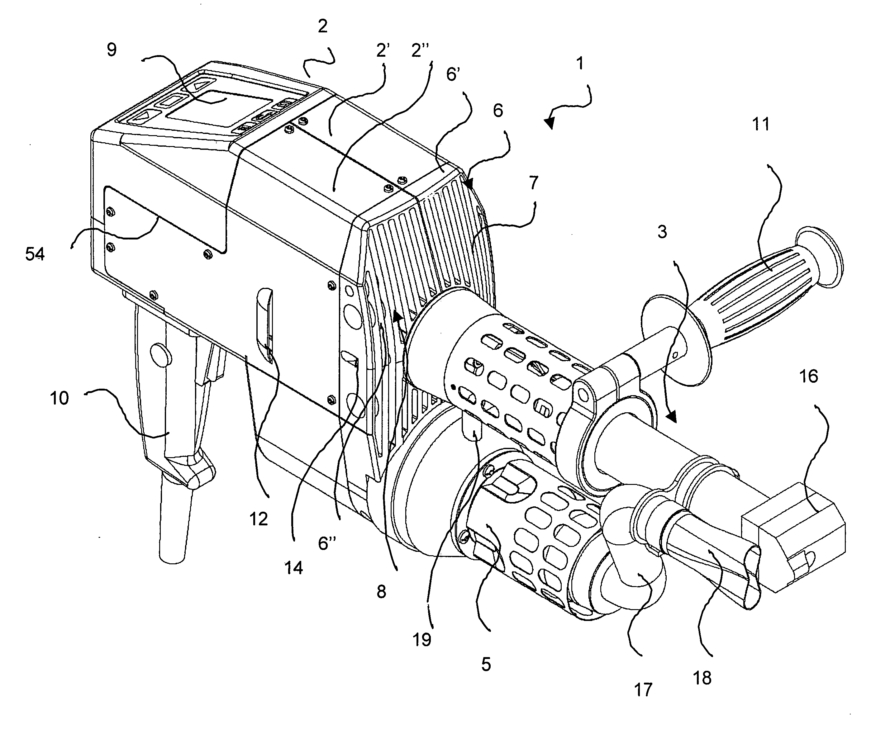
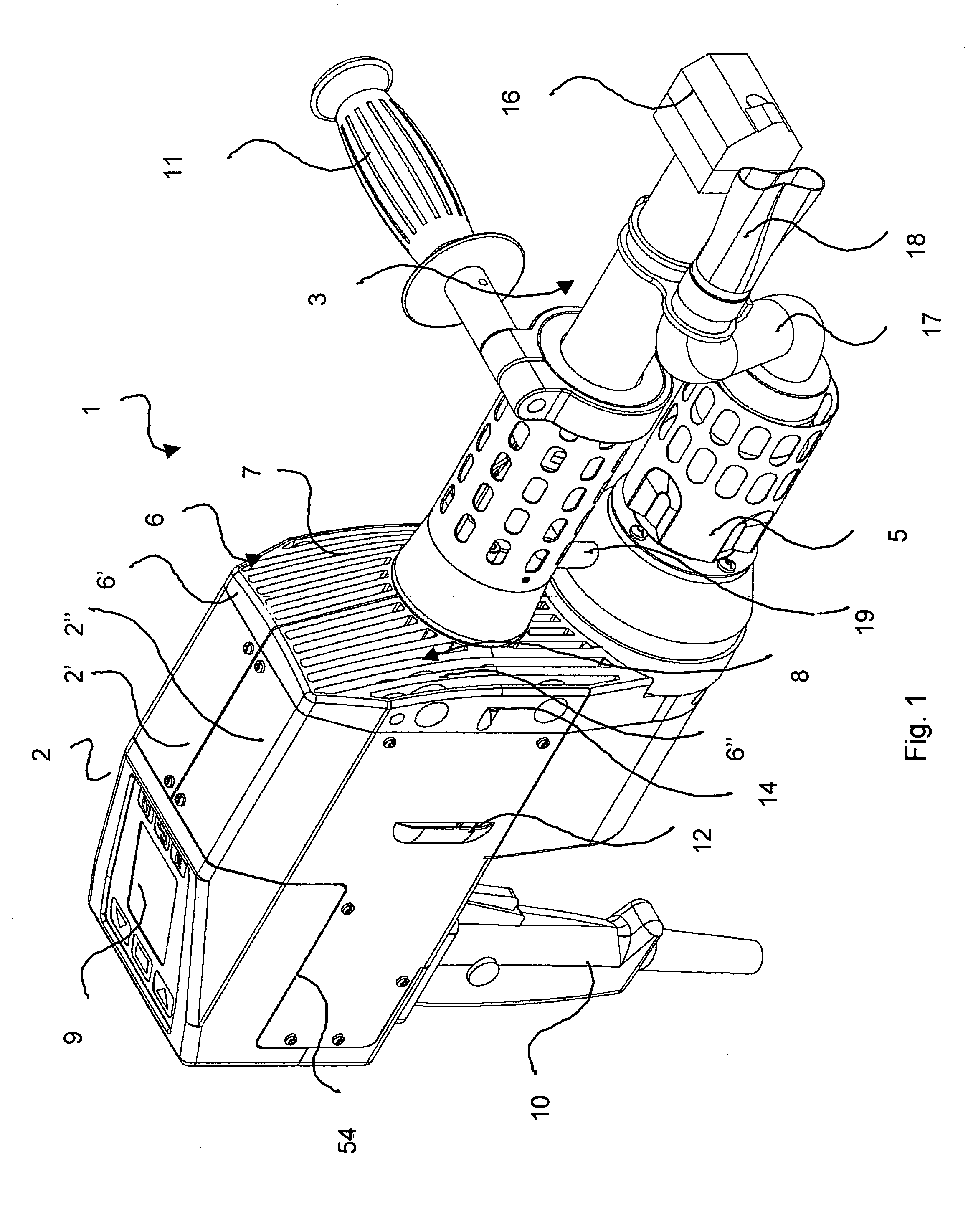
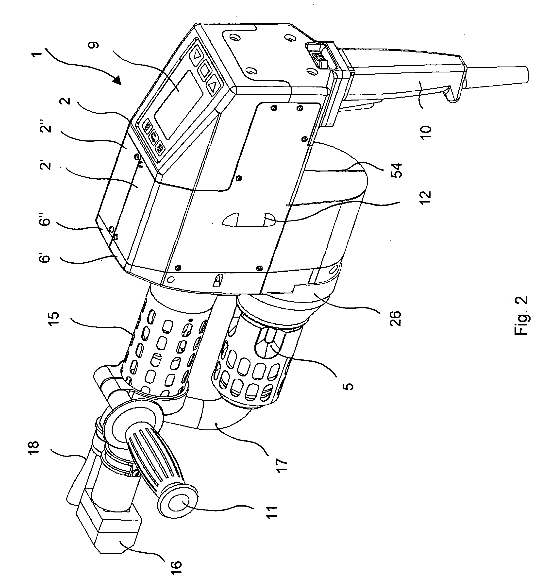
[0023] The FIGS. 1 and 2 show the handheld extruder welding device 1 from various angles with a housing 2 where the screw housing 3 surrounding the extruder screw 4 (FIG. 3) and the heater housing 5 are protruding from its front side. On the side facing the extruder screw 4 and the heater housing 5, the housing 2 has a two-part cooling body 6 with cooling fins 7 and air inlets 8. As shown by the seams 54, the housing 2 includes of two housing halves 2′ and 2″ that are supported by the cooling body 6 as the base component. An electronic display 9 and a handle 10 are located on the housing. An additional handle 11 for the other hand of the operator is attached to the screw cylinder 3. On their sides, both housing halves 2′, 2″ each have an outlet opening 12 for the warm air coming from the drive motor 13 (FIG. 13) of the extruder screw 4 that is located inside. Each side of the cooling body 6 has a feed opening 14 for the welding wire. In a first section following the housing 2, the s...


PUM

PropertyMeasurementUnit
Fractionaaaaaaaaaa
Forceaaaaaaaaaa

Abstract

Handheld extruder welding device for welding thermoplastic synthetic materials, including an extruder screw, a drive system for the extruder screw in an axial extension of the extruder screw, and a hot air unit with a blower, where the blower and the drive system are integrated in a housing including several parts, and where a cooling body with air inlets is located on the housing on the screw side. This cooling body transfers the axial and radial forces between the drive system and the screw cylinder and supports the housing. In this handheld extruder welding device, all drive components are integrated in one housing which makes it suitable for robust use and a long service life. Its design with a cooling body as the support base for the entire device represents a special function.

Description

TECHNICAL FIELD [0001] This invention concerns a handheld extruder welding device for welding thermoplastic synthetic materials, including an extruder screw, a drive system for the extruder screw in an axial extension of the extruder screw, and a hot air unit for producing hot air for pre-heating. BACKGROUND OF THE INVENTION [0002] Such handheld extruder welding devices are familiar devices, and are used primarily for welding plastic panels or similar objects. The known plastic welding devices consist essentially of a handheld drill serving as the drive system and a removable attachment for this drill. In the attachment, a strand of plastic in the shape of a plastic wire that is supplied via one or several feed channels and a feed device is first chopped up, and is then heated in a conveying device—usually in form of a worm conveyor—and a plasticizing device so that the chopped plastic material reaches a plastic state and is then expelled as welding material through a welding shoe. ...

Claims


Application Information

Patent Timeline
IPC IPC(8): B28B3/00B05C17/005B29C48/02B29C48/03B29C48/395
CPCB29C47/0002B29C47/0009B29C47/1054B29C66/861B29C65/40B29C66/0242B29C47/38B29C48/02B29C48/03B29C48/2888B29C48/395
Inventor MICELI, GUISEPPE DEARNOLD, HANSNIEDERBERGER, ADOLP
Owner LEISTER TECHNOLOGIES
Why Eureka
Try Eureka