Solar photovoltaic mirror modules

a technology of solar photovoltaic mirrors and modules, applied in photovoltaic supports, pv power plants, sustainable buildings, etc., can solve the problems of special cell and module manufacturing facilities investment, and achieve the effect of reducing cost and triple module production

Inactive Publication Date: 2006-03-16
JX CRYSTALS
View PDF63 Cites 115 Cited by
  • Summary
  • Abstract
  • Description
  • Claims
  • Application Information

AI Technical Summary

Benefits of technology

[0007] The present invention provides a 3-sun mirror module design that uses ⅓ the cells to triple module production at lower cost.

Problems solved by technology

A problem for concentrated sunlight PV systems has been the requirement for investment in special cell and module manufacturing facilities.

Method used


Image

  • Solar photovoltaic mirror modules
  • Solar photovoltaic mirror modules
  • Solar photovoltaic mirror modules

Examples


Embodiment Construction

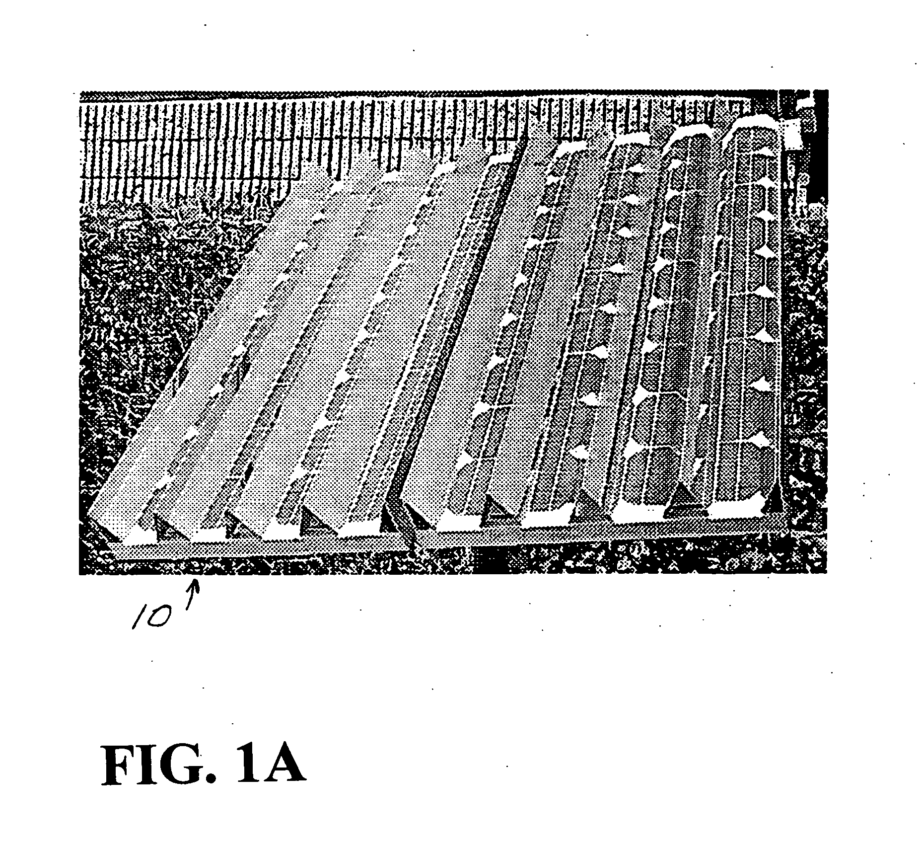
[0041] A photograph of the 2× mirror modules 10 is shown in FIG. 1A.

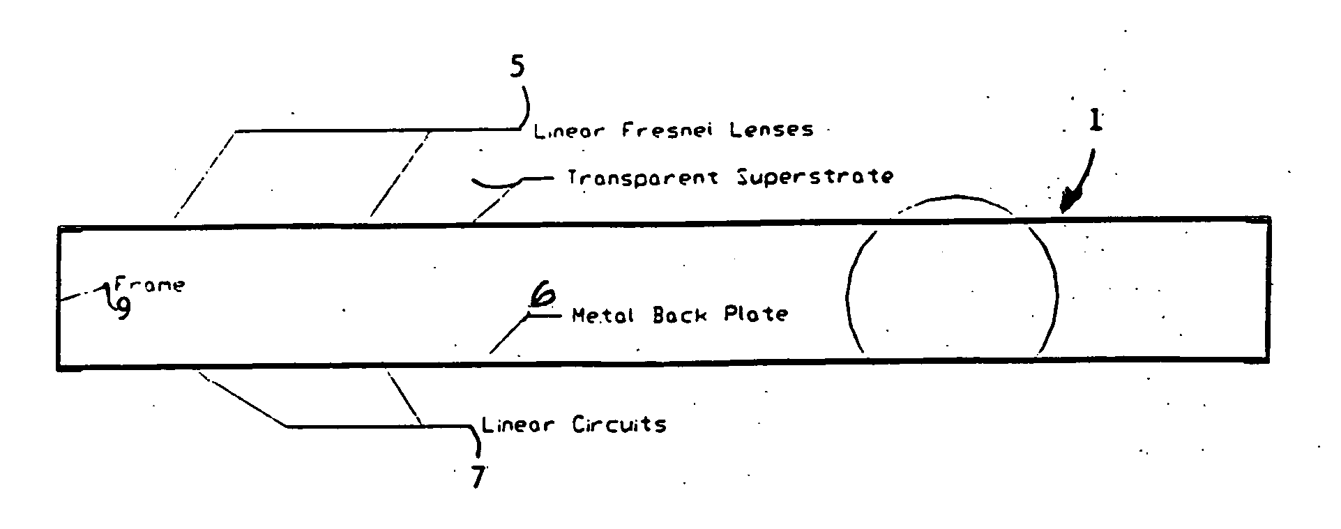
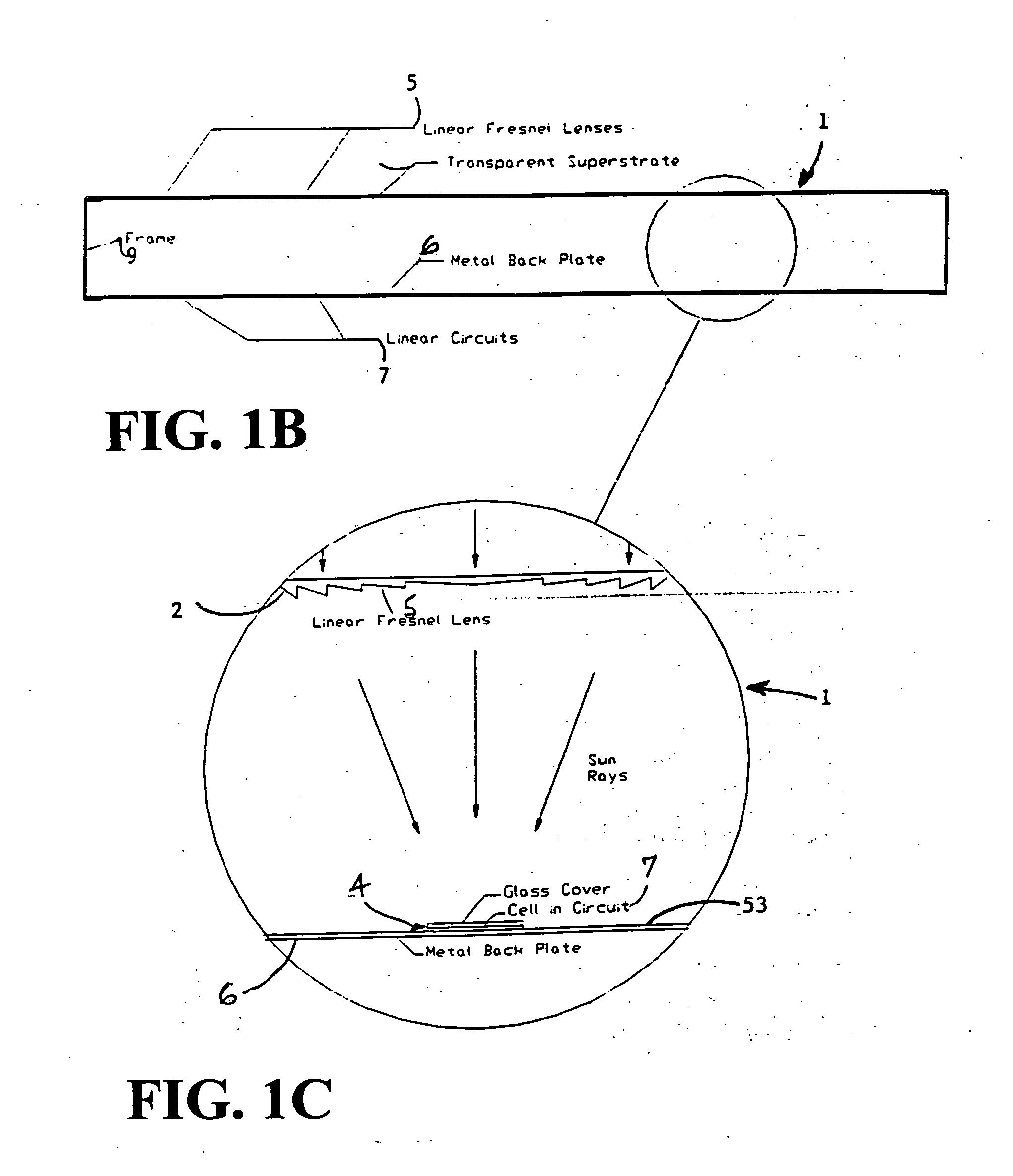
[0042]FIG. 1B shows a cross section through a planar solar concentrator power module 1. The cross section is perpendicular to the focal lines produced by the lenses and perpendicular to the circuit length dimension. FIG. 1C shows a blow up section from FIG. 1B showing a single lens 2 and circuit element 4 in more detail. The preferred planar concentrator solar module consists of a back panel of metal sheet 6 upon which linear silicon cell circuits 7 are mounted. In the exemplary embodiment depicted, for example, a metal frame 9, for example aluminum frame, surrounds the module 1 with the cells 4 of the cell circuits 7 mounted on the back panel 6. A lens array 3 of, for example, Fresnel lenses 5 is mounted on a glass front sheet 8 forming the front side of the planar concentrator solar module 1. The array 3 of linear Fresnel lenses 5 produces lines of focused solar radiation that fall on an aligned array of linear p...


PUM


Abstract

A planar concentrator solar power module has a planar base, an aligned array of linear photovoltaic cell circuits on the base and an array of linear Fresnel lenses or linear mirrors for directing focused solar radiation on the aligned array of linear photovoltaic cell circuits. The cell circuits are mounted on a back panel which may be a metal back plate. The module includes a voltage stand-off layer and heat spreader layer. The cell circuit array may include multiple sets of cells formed by dividing planar silicon cells. The cell circuit area is less than a total area of the module. Each linear lens or linear mirror has a length greater than a length of the adjacent cell circuit. The circuit backplate is encapsulated by lamination for weather protection. The planar module is generally rectangular with alternating rows of linear cell circuits and linear lenses or linear mirrors.

Description

[0001] This application claims the benefit of U.S. Provisional Application No. 60 / 608,517 filed Sep. 10, 2004, which is incorporated herein by reference in its entirety. [0002] Co-pending U.S. application Ser. No. 10 / 209,900, filed Aug. 2, 2002, which claims benefit of U.S. Provisional application No. 60 / 374,808 filed Apr. 24, 2002 and U.S. Provisional Application No. 60 / 391,122 filed Jun. 25, 2002, are all incorporated herein by reference in each of their entireties. [0003] WO 2004 / 001859 A1 publication of PCT / US03 / 19524 is also incorporated herein by reference in its entirety.BACKGROUND OF THE INVENTION [0004] Solar concentrators require very high investments to scale up production of a new concentrator cell. The investment required for manufacturing scale-up versions of a new cell is prohibitive. Another problem that needs to be solved is the cell-interconnect problem. [0005] There is a need for a solar concentrator module that is a retrofit for a planar module and that is easier...

Claims


Application Information

Patent Timeline
Patent Type & Authority Applications(United States)
IPC IPC(8): H01L31/00
CPCH01L31/042H01L31/048H01L31/052H01L31/0547H02S20/00H01L31/0543Y02E10/52H01L31/0521H02S20/23Y02B10/10
Inventor FRAAS, LEWIS M.FRAAS, JANY X.HUANG, HAN XIANGAVERY, JAMES E.
Owner JX CRYSTALS
Why Eureka
Try Eureka