
Wheel flange lubrication system

Active Publication Date: 2006-03-16
PHYMET
View PDF18 Cites 9 Cited by
  • Summary
  • Abstract
  • Description
  • Claims
  • Application Information

AI Technical Summary

Benefits of technology

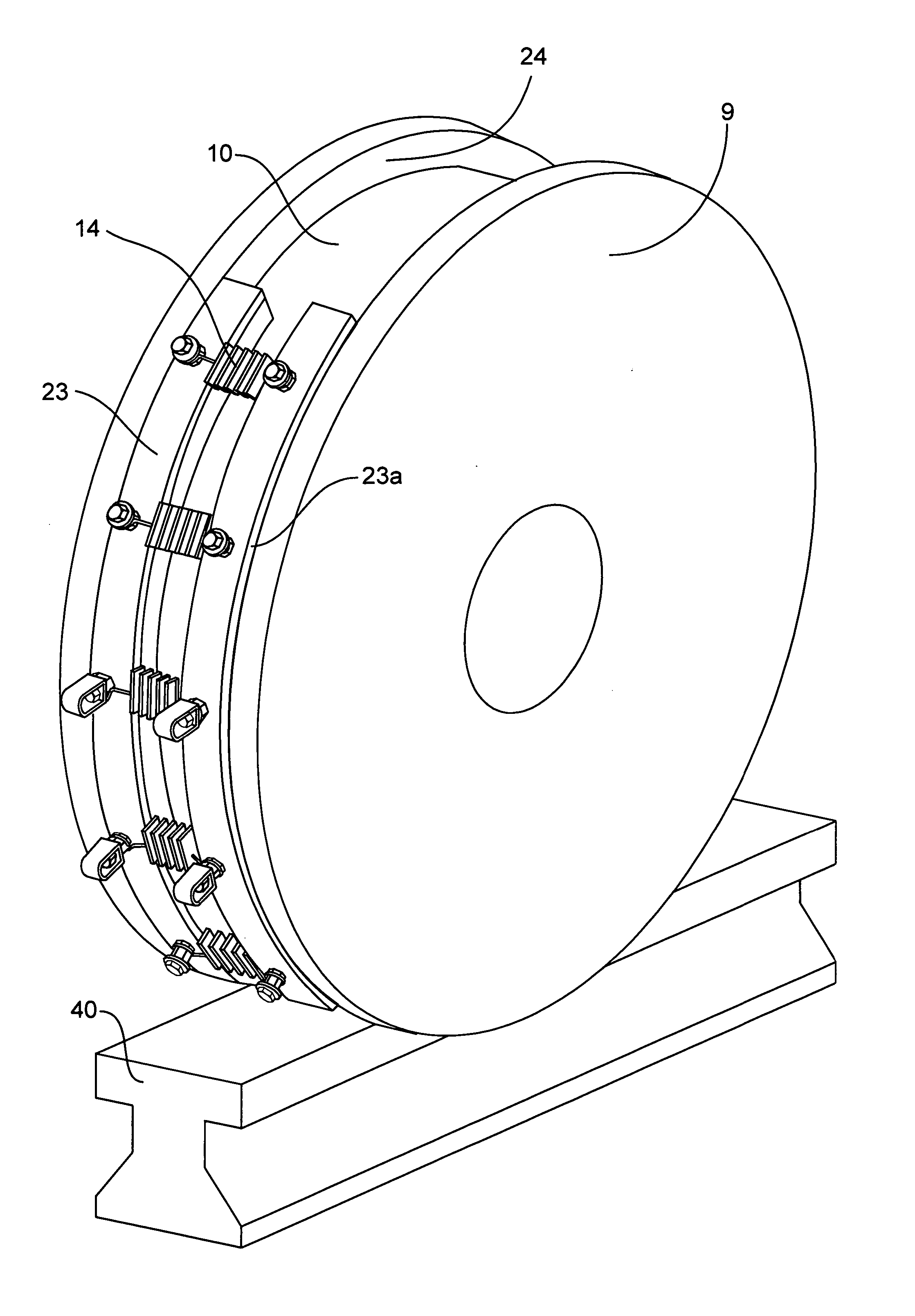
[0007] A rigid block of lubricant is provided with a holder for directing a contact side of the block against the wheel flange. A method and means are provided to force the contact side of the lubricant block laterally against the wheel flange and radially into the crotch of the wheel. The rigid block has independent radial and lateral force means for improved control of the position of the block. A significant improvement in lubrication control is achieved by providing means to adjust the forces used to position and direct the lubrication block. Improved control minimizes lubricant contact on the tread of the wheel or on the rail. A preferred design is the use of a curved block or segment blocks to provide an arc length of at least 5 degrees relative to the wheel radius.

Problems solved by technology

Friction between rails and wheels is known to increase the wear on the wheel flange and increase fuel consumption.
Lubricants which are not solid (greases and liquids) have many disadvantages including; storing and refilling the lubricant container, controlling the amount applied and dealing with environmental concerns with lubricant on the track.
The amount of lubricant being shared with subsequent wheel flanges is not easily controlled.
It is well known that misalignment will occur between the rail and wheel flange due to the vertical and horizontal movements of the wheel.
Rail alignment will also contribute to wheel flange wear.
The use of a lubricant block or stick has eliminated some of these problems but still has not been completely successful.
It has been difficult to mount these devices on board a rail vehicle or crane and control where the lubricant stick is positioned to insure the lubrication is applied to the flange.
Previous sticks have had their tips pushed against the wheel flange and have not had their position controlled to compensate for the normal wheel movement and curvature of the track.
The capability to adjust the forces and direction on the stick has been lacking.
Applying lubricant to a wheel flange which is subject to a great range of movement has created a need not solved by previous lubricant stick or block application systems.

Method used


Image

  • Wheel flange lubrication system
  • Wheel flange lubrication system
  • Wheel flange lubrication system

Examples


Embodiment Construction

[0018] The following description is a preferred embodiment by way of example only and without any limitation to the combination of features for carrying out the invention.

[0019] The present invention relates to a system for lubricating wheel flanges using a rigid lubrication block. Various lubricants may be used including microporous polymeric lubricants, graphite, molybdenum disulfide, impregnated polymers, solid grease, sponge, sintered bronze, impregnated felt, PTFE (PolyTetraFluoroEthylene) and UHMWPE (UltraHighMolecularWeightPolyEthylene). Other lubricants may also be used. A preferred lubricant is the microporous polymeric lubricant which has excellent wear characteristics and provides a controlled release of the lubricant from the block. This type of material is taught in U.S. Pat. Nos. 3,541,011; 3,547,819; and 3,729,415.

[0020] The lubricant block or stick is composed of at least 30% solids. The lubricant block may have various shapes. The shape, amount of surface contact,...


PUM


Abstract

A wheel flange lubrication system for rail vehicles is described consisting of a rigid lubrication block, which is forced against a wheel flange to provide lubrication to the wheel flange. The block or stick is maintained in position to reduce flange wear, to minimize the movement of lubricant to undesirable locations, such as the crown of the rails and the tread of the wheel, and to provide a lubrication system which is environmentally safe. Preferably the lubrication block is arc shaped and spring-forced laterally and radially into the flange. The lubrication system is designed to stay in contact with the wheel flange and apply the desired amount of lubrication in the flange area using the side contact surface of the block. This adjustable position control is provided by applying independent forces which are directed radially towards the crotch of the wheel and laterally towards the wheel flange. The lubrication system is applicable to single or two flange wheels.

Description

RELATED APPLICATION [0001] This patent application is based on and claims priority of provisional patent application Ser. No. 60 / 585984, filed on Jul. 7, 2004.TECHNICAL FIELD [0002] The present invention relates in general to systems for lubricating wheel flanges on railroad vehicles, overhead cranes, trolleys and other equipment traveling on rails. In particular, the system relates to lubrication of wheel flanges using a rigid lubricant block or stick. BACKGROUND OF THE INVENTION [0003] Friction between rails and wheels is known to increase the wear on the wheel flange and increase fuel consumption. It has long been known to apply lubricant to a wheel flange to reduce the friction and wear between a vehicle wheel and a rail. Lubricants which are not solid (greases and liquids) have many disadvantages including; storing and refilling the lubricant container, controlling the amount applied and dealing with environmental concerns with lubricant on the track. Most of these systems also...

Claims


Application Information

Patent Timeline
IPC IPC(8): B61K3/00
CPCB66C9/08B61K3/02
Inventor LACERDA, MARIOCOLLINS, BRANDON MICHAEL
Owner PHYMET
Learn More