Communication apparatus

a technology of communication apparatus and communication line, which is applied in the direction of power distribution line transmission, using reradiation, instruments, etc., can solve the problems of not being able to justify intermediate requirements, high cost, and not being able to meet modest update rates

Active Publication Date: 2006-03-16
BAKER HUGHES ENERGY TECH UK LTD
View PDF11 Cites 6 Cited by
  • Summary
  • Abstract
  • Description
  • Claims
  • Application Information

AI Technical Summary

Problems solved by technology

This well-proven technology has been more than adequate for the modest update rates historically required.
However, the cost is high and cannot always be justified for intermediate requirements.

Method used


Image

  • Communication apparatus
  • Communication apparatus

Examples


Embodiment Construction

[0014] The following embodiment permits two-way high speed communication at typically 115 kbits / sec and two-way low speed communication at typically 1.2 kbits / sec, simultaneously via the same umbilical conductors, i.e. a dual band system. The invention is applicable to both conventional two wire and (COP) systems and has particular value in enhancing an existing low speed system.

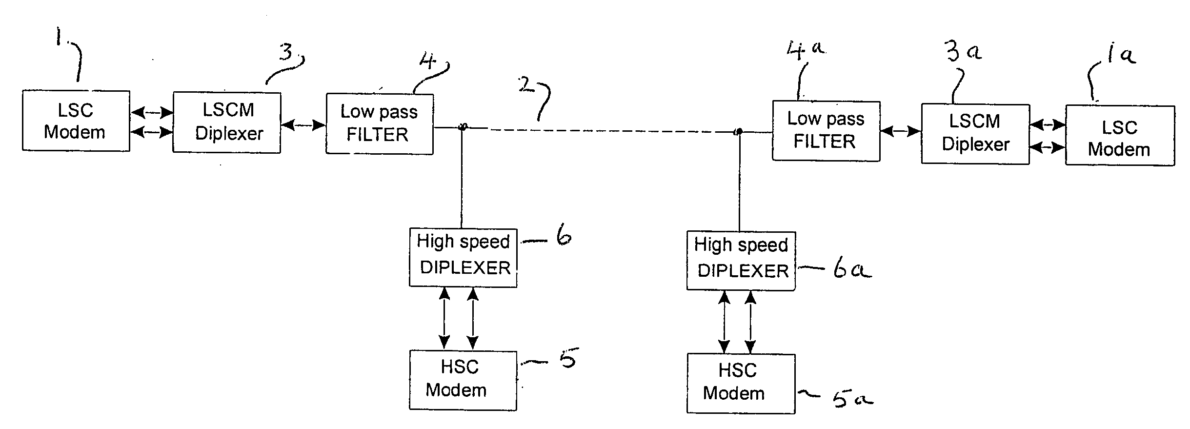
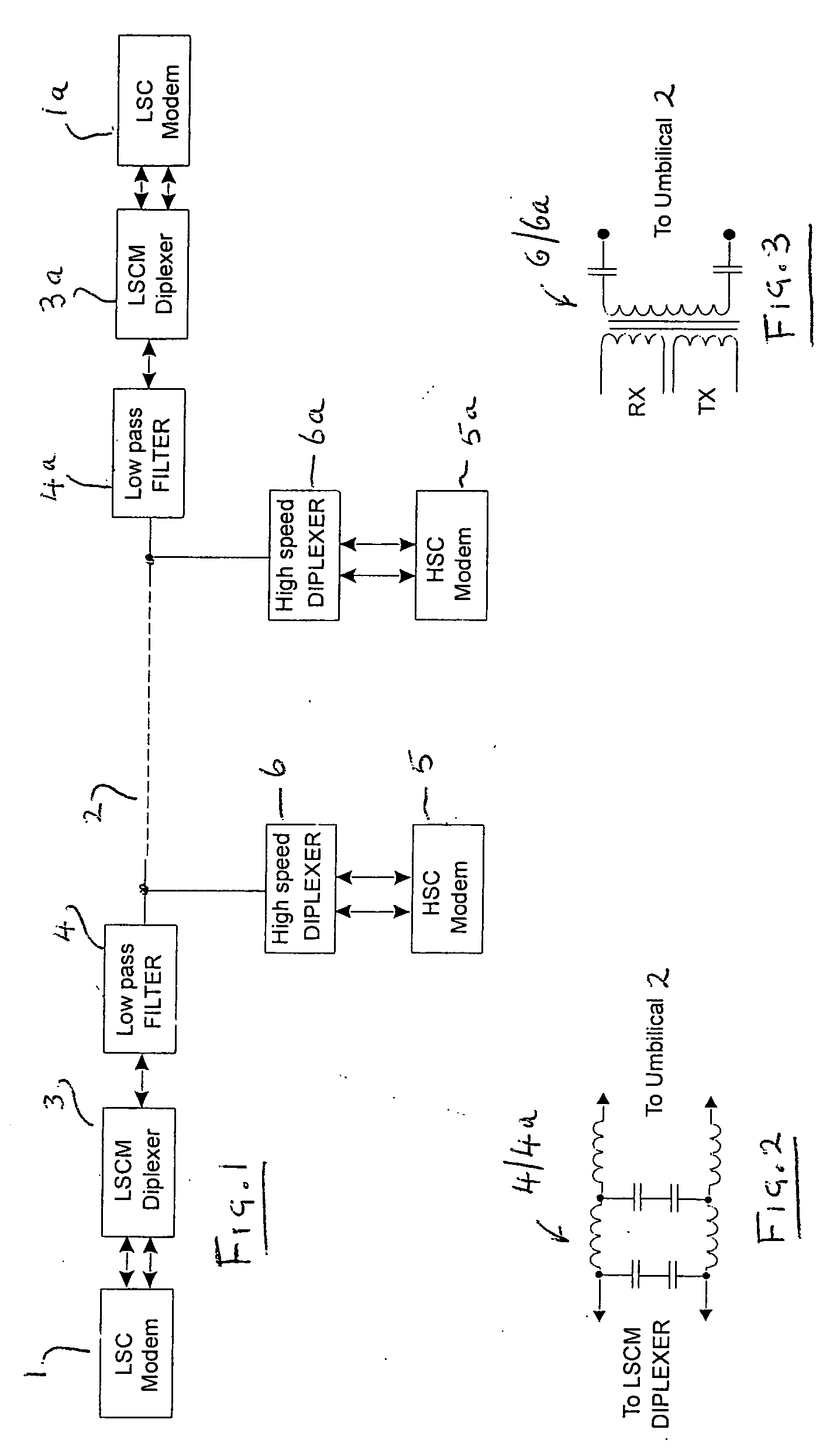
[0015] Referring to FIG. 1, at for example at a surface facility in a control system for a subsea hydrocarbon extraction well, a low speed copper (LSC) modem 1 is connected to an umbilical 2 via a low speed copper modem (LSCM) diplexer 3 and a low pass filter 4. Also, a high speed copper (HSC) modem 5 is connected to the same umbilical 2 via a high speed diplexer 6. Typically, modem 1 operates at 1.2 kbits / sec and modem 5 at 115 kbits / sec. This configuration is repeated at the other end of the umbilical 2, for example at an underwater facility such as a well tree—see LSC modem 1a, diplexer 3a, low pass filt...


PUM


Abstract

A communication system transmits data in a control system for an underwater fluid well. A communications link is located between first and second facilities of the well. A data transmitter for transmitting data from one of the facilities to the other via the communications link has both a relatively high speed modem and a relatively low speed modem.

Description

CROSS-REFERENCE TO RELATED APPLICATION [0001] This application claims the benefit of United Kingdom Patent Application No. 0418856.1, filed on Aug. 24, 2004, which hereby is incorporated by reference in its entirety. TECHNICAL FIELD OF THE INVENTION [0002] The present invention relates to communication apparatus, more particularly communication apparatus for transmitting data in a control system for an underwater fluid well, such as a hydrocarbon extraction well. BACKGROUND OF THE INVENTION [0003] Traditionally, subsea hydrocarbon production control systems have relied upon low data rate, wire-based telemetry for communication via umbilicals connecting the surface and subsea facilities. This well-proven technology has been more than adequate for the modest update rates historically required. The use of “communications on power” (COP) offered a useful cost saving for the umbilicals. [0004] Recently, the advent of more demanding control and instrumentation requirements for production ...

Claims


Application Information

Patent Timeline
Patent Type & Authority Applications(United States)
IPC IPC(8): G01V3/00H04L5/16H04B3/54H04M
CPCH04B2203/5475H04B3/54Y04S40/121Y02E60/00E21B4/12H02J13/00H04B3/56
Inventor CAUSIER, STEPHEN JAMES
Owner BAKER HUGHES ENERGY TECH UK LTD
Why Eureka
Try Eureka