Antenna measurement systems

a measurement system and antenna technology, applied in the field of antenna radiation pattern measurement, can solve the problems of minor distortion of the measured sidelobe structure, high and high cost of specialist design and construction skills, and achieve the effect of eliminating or reducing the cost of the antenna rang

Inactive Publication Date: 2006-03-16
LEATHER PAUL S H DR +2
View PDF7 Cites 54 Cited by
  • Summary
  • Abstract
  • Description
  • Claims
  • Application Information

AI Technical Summary

Benefits of technology

[0012] It is the aim of the present invention to provide an antenna measurement system that eliminates, or at least substantially reduces, the effects of echoing or multipath.

Problems solved by technology

An antenna range is a costly facility that requires specialist design and construction skills, space, regular maintenance and calibration, skilled personnel and resource management.
Small phase deviations result in minor distortions of the measured sidelobe structure while larger deviations cause major errors in the measured gain and lobe structure.
Large separation distances, as mentioned above, increase the probability of unwanted multipath reflections from the ground and other scatterers, reaching the antenna under test.

Method used


Image

  • Antenna measurement systems
  • Antenna measurement systems
  • Antenna measurement systems

Examples


Embodiment Construction

[0060] The invention is applicable to existing indoor and outdoor measurement ranges and typical examples of these are described briefly hereinafter and in particular how the present invention is applied thereto.

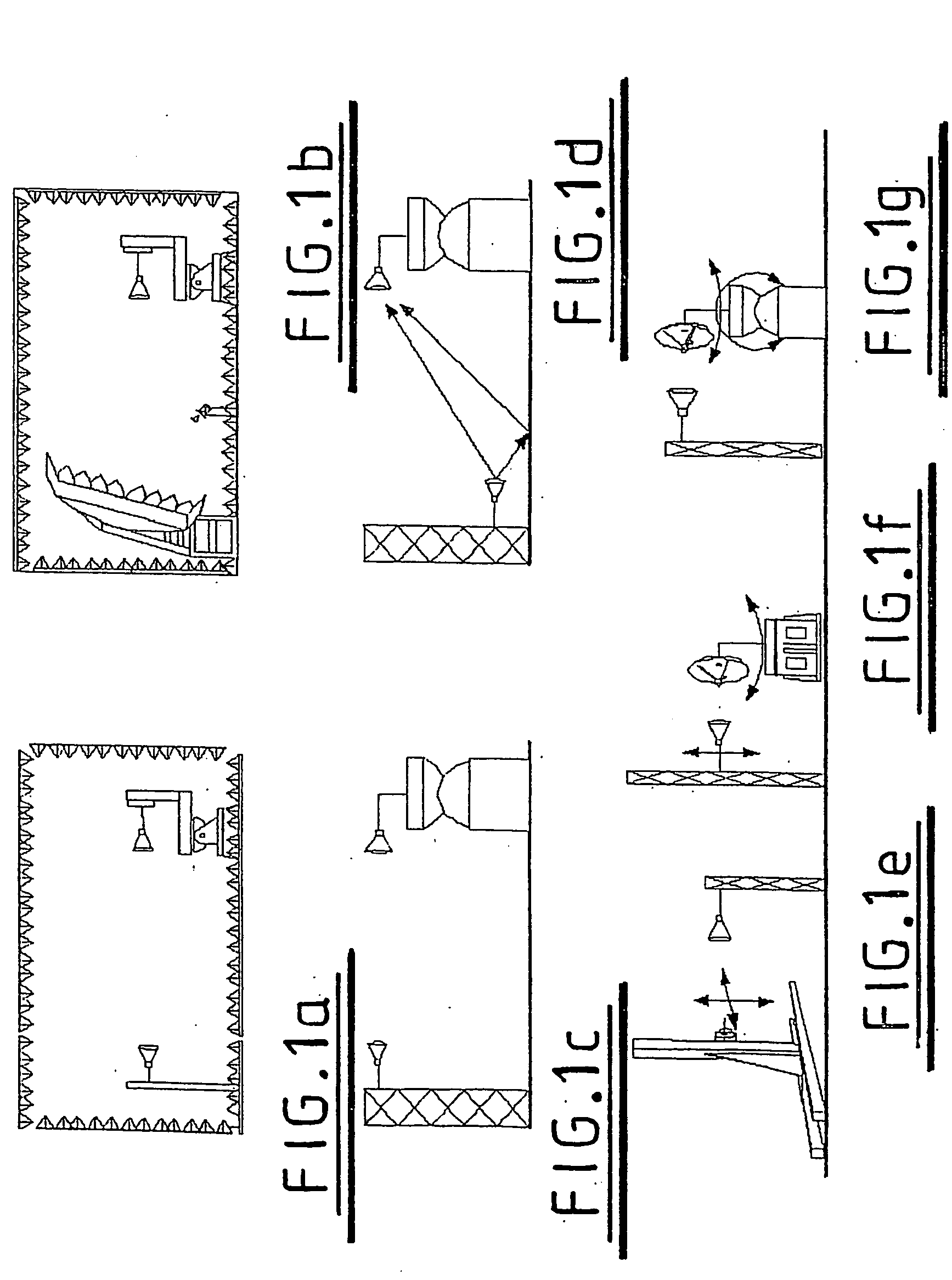
[0061] Referring firstly to FIGS. 1a-1g. Seven commonly used antenna ranges are illustrated. They comprise a rectangular anechoic chamber (FIG. 1a), a compact antenna test range (FIG. 1b), an outdoor elevated range (FIG. 1c), a ground reflecting range (FIG. 1d), a planar near-field test range (FIG. 1e), a cylindrical near-field test range (FIG. 1f), and a spherical near-field test range (FIG. 1g). Save for the changes that application of the present invention has, their construction and how they are used to test antennas is not described in any detail as it is well known in the art.

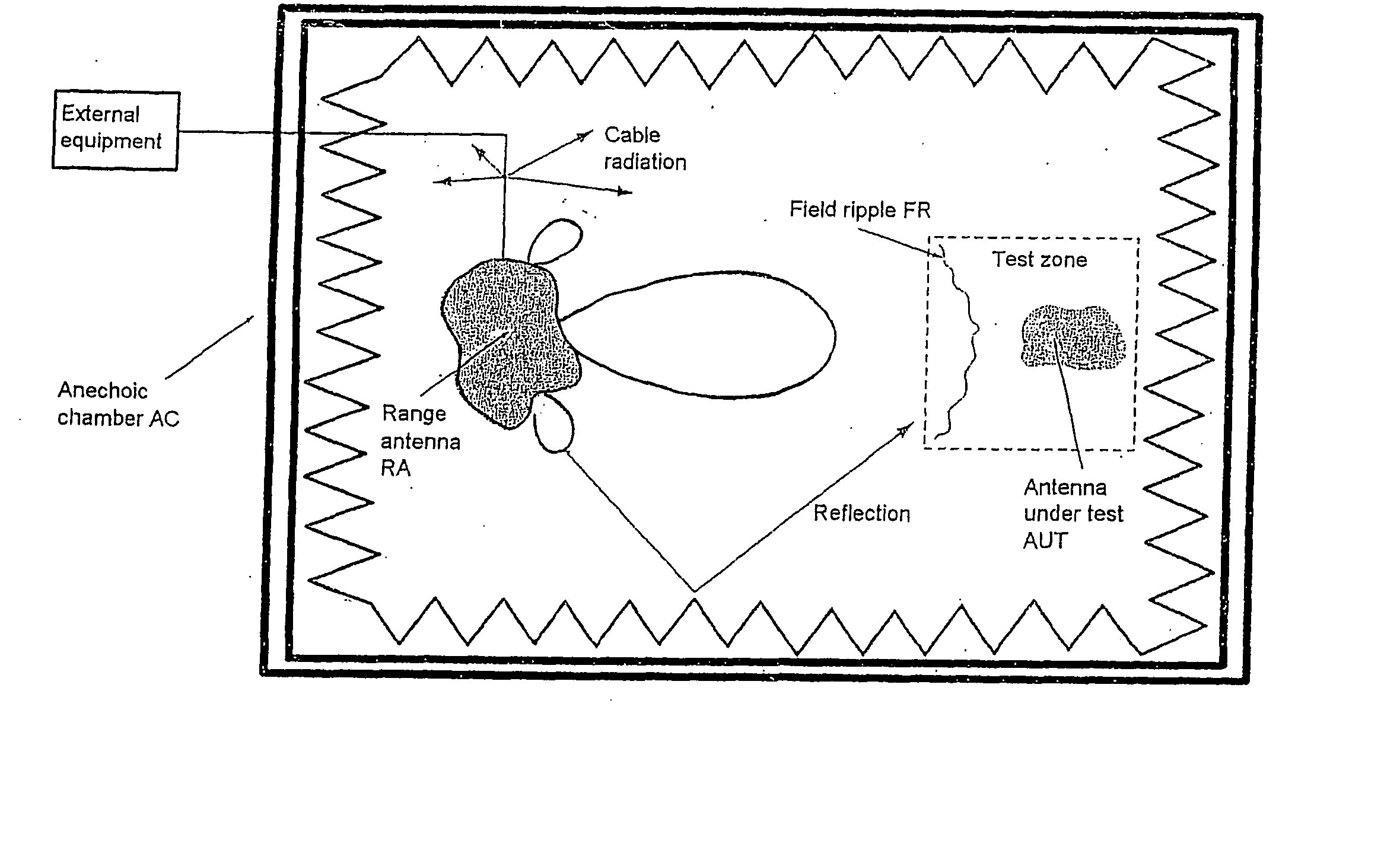
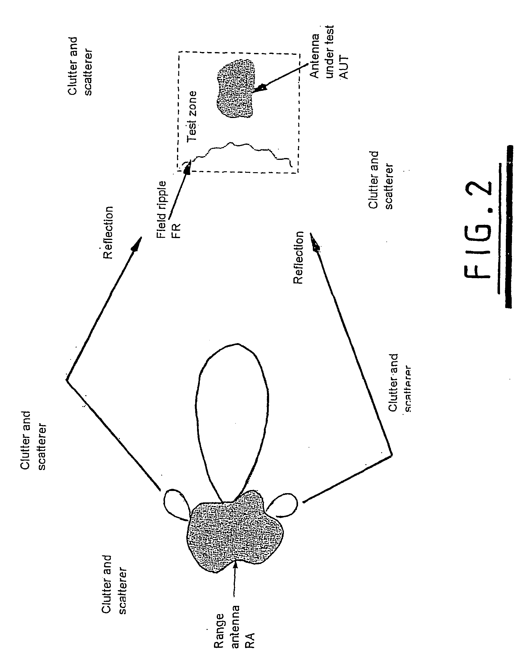
[0062]FIG. 2 is a simplified two-dimensional representation of an outdoor antenna measurement range showing the range antenna RA and the measurement object or antenna under test AUT. In the test...


PUM


Abstract

An antenna measurement range and a method of calibrating same is proposed which at least substantially reduces the effects of echoing or multi path. The method of calibrating the range comprises the steps of: generating and radiating a training signal; receiving the radiated training signal and comparing the received signal with the expected signal; determining a set of equaliser coefficients to be used in these circumstances to eliminate or minimise the error between the expected training signal and the received signal; and storing the set of equalisation coefficients and associating them with the rotational or translational position of the antenna under test so that the coefficients can be applied to subsequent radiation pattern measurements. In one embodiment, the measurement nodes are dispersed in a three dimensional array about the antenna under test and a set of coefficients arrived at for each node to be applied to the subsequent radiation pattern measurements.

Description

PRIORITY INFORMATION [0001] The present application claims priority from PCT Application Ser. No. PCT / GB02 / 05793, filed on Dec. 19, 2002, which claims priority from Great Britain Patent Application Ser. No. 0130842.8, filed Dec. 21, 2001. The contents of these applications are incorporated herein in their entireties by reference thereto.FIELD OF THE INVENTION [0002] The present invention relates to the measurement of antenna radiation patterns. BACKGROUND OF THE INVENTION [0003] By definition, radio communication systems contain antennas that serve as transducers between the radio frequency (RF) energy within the system and the radiated energy between systems. The antennas used must be compatible with the requirements of the particular RF system. While this results in a variety of designs for various communication systems, most antennas can be characterized by a common set of antenna performance parameters. [0004] In order to select or design an antenna suitable for a given communic...

Claims


Application Information

Patent Timeline
Patent Type & Authority Applications(United States)
IPC IPC(8): G01S7/40G01R29/10H01Q3/26
CPCH01Q3/267G01R29/105
Inventor LEATHER, PAUL SIMON HOLTPARSONS, JOHN DAVID
Owner LEATHER PAUL S H DR
Why Eureka
Try Eureka