Beam scanning device with light blocking member

a beam scanning and light blocking technology, applied in the field of beam scanning devices and image forming apparatuses, can solve the problems of abnormal image, metal-molded products are not shaped well, lens inevitably has a foreign shape, etc., to prevent image quality degradation, good heat releasing performance and anti-vibration performance, and the effect of sufficient accuracy

Active Publication Date: 2006-03-16
RICOH KK
View PDF8 Cites 4 Cited by
  • Summary
  • Abstract
  • Description
  • Claims
  • Application Information

AI Technical Summary

Benefits of technology

[0031] According to at least one embodiment of the present invention, with the provision of the light blocking member, it is possible to block the flare light of synchronization-purpose pre-lit light with sufficient accuracy despite the use of the metal optical housing. This prevents image quality from degrading due to the flare light while ensuring good heat releasing performance and anti-vibration performance.

Problems solved by technology

If there is a discontinuous surface outside the effective lens area, the flare light of such a discontinuous surface may enter the imaging area on the image carriers, resulting in the problem of an abnormal image.
Since the shape of the inlet (gate) through which the resin is poured is different from the shape of the lens, the resulting lens inevitably has a portion with foreign shape.
This gives rise to the problem that the flare light of the discontinuous surface enters the imaging area on the image carriers to create an abnormal image.
In general, metal-molded products are not shaped well compared with resin-molded products, and it is difficult to create a product having thin thickness.

Method used


Image

  • Beam scanning device with light blocking member
  • Beam scanning device with light blocking member
  • Beam scanning device with light blocking member

Examples


first embodiment

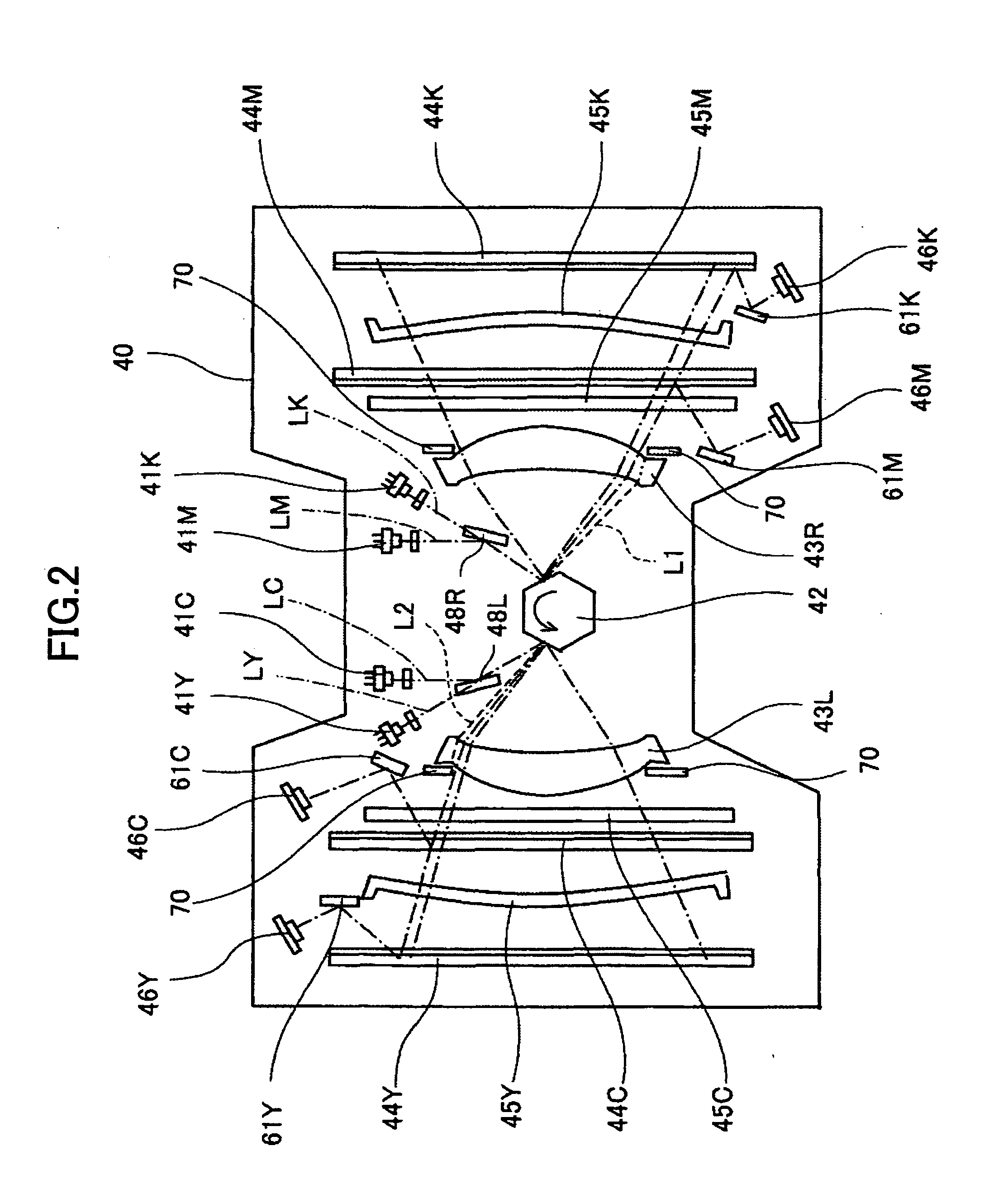
[0054] In the following, the beam scanning device 4 according to the present invention will be described with reference to FIG. 2 and FIG. 3. FIG. 2 is a plan view for explaining the internal structure of the beam scanning device. FIG. 3 is a lateral view of the beam scanning device.

[0055] The beam scanning device 4 includes, inside a metal housing 40, four laser units 41Y, 41M, 41C, and 41K serving as light sources for shining laser beams LY, LC, LM, LK (which will be referred to as “laser beams L” when there is no need for distinction) on the respective photoconductive drums 2. Two polygon mirrors 42a and 42b (which will be referred to as “polygon mirrors 42”) are provided to serve as a beam deflecting unit to deflect and scan the laser beams from the laser units 41 modulated in response to image signals, thereby forming two pairs of deflective scans on the two respective right / left sides, each pair being comprised of an upper part and a lower part. An fθ lens 43L and fθ lens 43R ...

second embodiment

[0074] In the following, the beam scanning device 4 according to the present invention will be described with reference to FIG. 8. FIG. 8 is a plan view for explaining the internal structure of the beam scanning device.

[0075] In the illustrated beam scanning device 4, the optical beams pass through the fθ lenses 43 of the optical system, and are then blocked by light blocking members 80 outside the effective scan area that includes the optical paths extending to the synchronization detecting sensors 46. Structures other than the structure of the light blocking members are the same as those of the beam scanning device of the first embodiment, and a description thereof will be omitted.

[0076] As illustrated in FIG. 9 and FIG. 10, the light blocking members 80 are provided on an exit side 43A of the fθ lens 43 to block an optical beam outside the effective scan area that include the synchronization-detection-purpose optical paths. The light blocking members 80 block the flare light tha...


PUM


Abstract

A beam scanning device includes a light source to emit a light beam, an optical deflector to deflect the light beam, an optical system including a fθ lens to guide the defected light beam to a scan surface to form an image thereon, a synchronization detecting sensor to detect the deflected light beam outside an area of the image, a light blocking member configured to block the deflected light beam on an exit side of said fθ lens outside an effective scan area that includes the area of the image and also includes an optical path extending to said synchronization detecting sensor, and a metal housing accommodating said light source, said optical deflector, said optical system, said light blocking member, and said synchronization detecting sensor.

Description

BACKGROUND OF THE INVENTION [0001] 1. Field of the Invention [0002] The present invention generally relates to a beam scanning device and an image forming apparatus. [0003] 2. Description of the Related Art [0004] General types of image forming apparatuses such as multifunction peripherals having the combined functions of printer / copier / facsimile device may include color image forming apparatuses, for example. Such color image forming apparatuses shine laser beams emitted from a plurality of light sources on four image carriers (e.g., photoconductive drums) arranged in parallel so as to create latent images. The latent images formed on the image carriers are developed with developers (e.g., yellow, magenta, cyan, black toners) for visualization. A transfer material such as a print paper sheet carried on a transfer conveyer belt passes successively through a series of transfer units corresponding to the respective image carriers. The visualized images in the respective colors formed ...

Claims


Application Information

Patent Timeline
Patent Type & Authority Applications(United States)
IPC IPC(8): G02B26/08
CPCG02B5/003G02B27/0018G02B26/123
Inventor SUGA, TOMOAKI
Owner RICOH KK
Why Eureka
Try Eureka