Eureka AIR delivers breakthrough ideas for toughest innovation challenges, trusted by R&D personnel around the world.

Suction set structure for bone surgery

a set structure and bone surgery technology, applied in mixers, medical science, vaccine/ovulation diagnostics, etc., can solve the problems of inconvenient medical personnel's task, further retarding the proceeding, and difficulty in removing the inner barrel b>11/b> from the suction handle, etc., to facilitate the removal and installation

Inactive Publication Date: 2006-03-16
PACIFIC HOSPITAL SUPPLY
View PDF2 Cites 11 Cited by
  • Summary
  • Abstract
  • Description
  • Claims
  • Application Information

AI Technical Summary

Benefits of technology

[0004] The present invention provides a suction set structure for bone surgery which facilitates the removal and installation of the inner barrel of a suction set. The chip bone collected inside the inner barrel will not slip out during the removal of the inner barrel. The inner barrel is also capable of standing upright after removal.
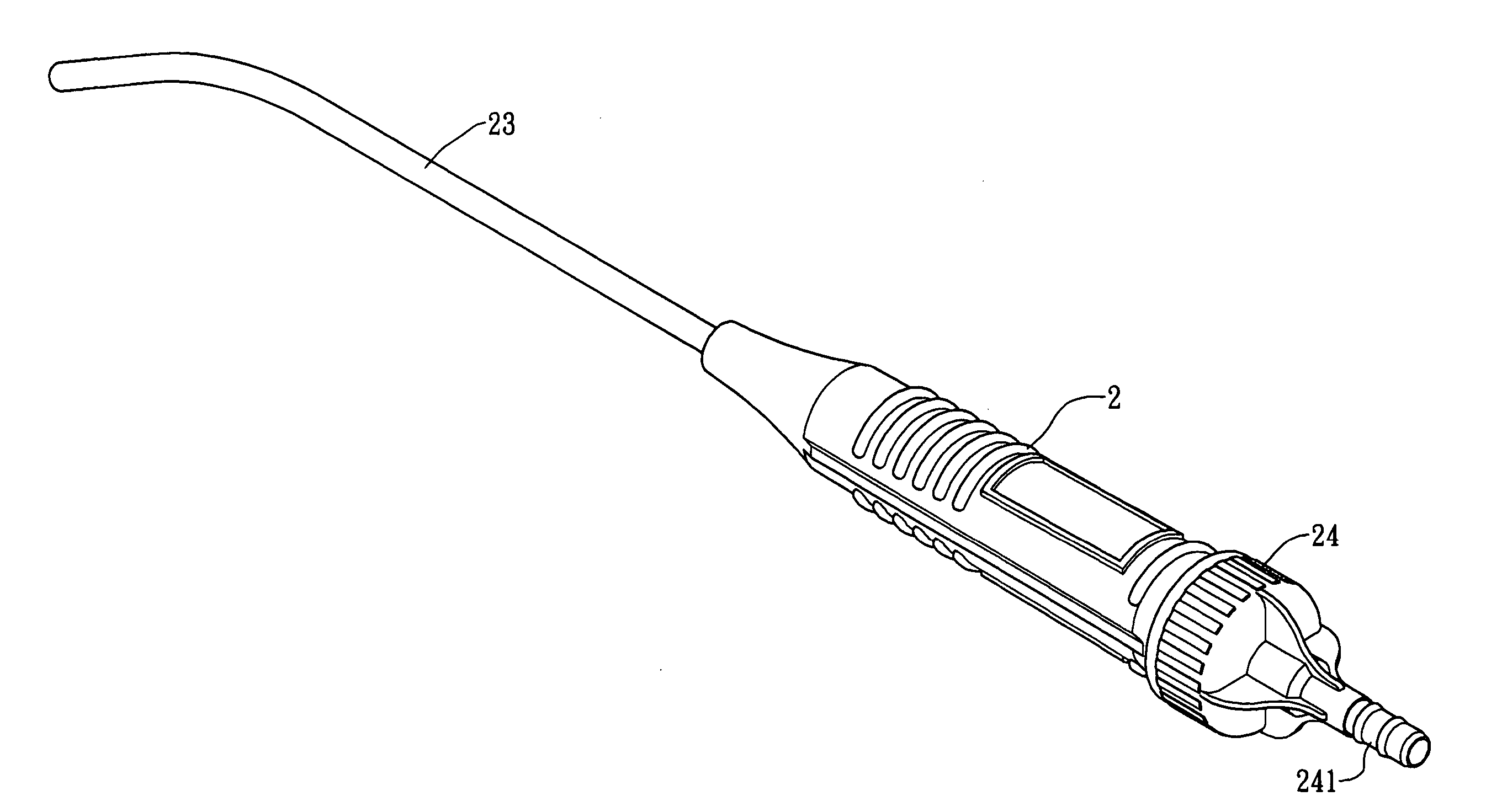
[0005] The suction set provided by the present invention includes a suction handle, a suction tip, an inner barrel with a fixing mount which is installed inside the suction handle, and a rear cap. The suction tip connects to a front open end of the suction handle. The front open end of the suction handle connects to an open end of the inner barrel. The inner barrel has a plurality of apertures which permit blood and bone dust to pass through and enter into the connecting tube of the rear cap while the larger bone chip is collected inside the inner barrel. The fixing mount is secured to the rear of the inner barrel, adjacent to a close end of the inner barrel. The fixing mount includes a ring portion, a connecting portion, and a rib flange extending from the ring portion. The rib flange is installed between the rear open end of the suction handle and the rear cap. By utilizing the present invention a medical person is able to vertically detach the rear cap and the inner barrel from the suction handle. The bone chip collected inside the inner barrel will not slip out during the removal of the inner barrel. Further, the inner barrel is able to erect upright on a platform by the rib flange of the fixing mount.

Problems solved by technology

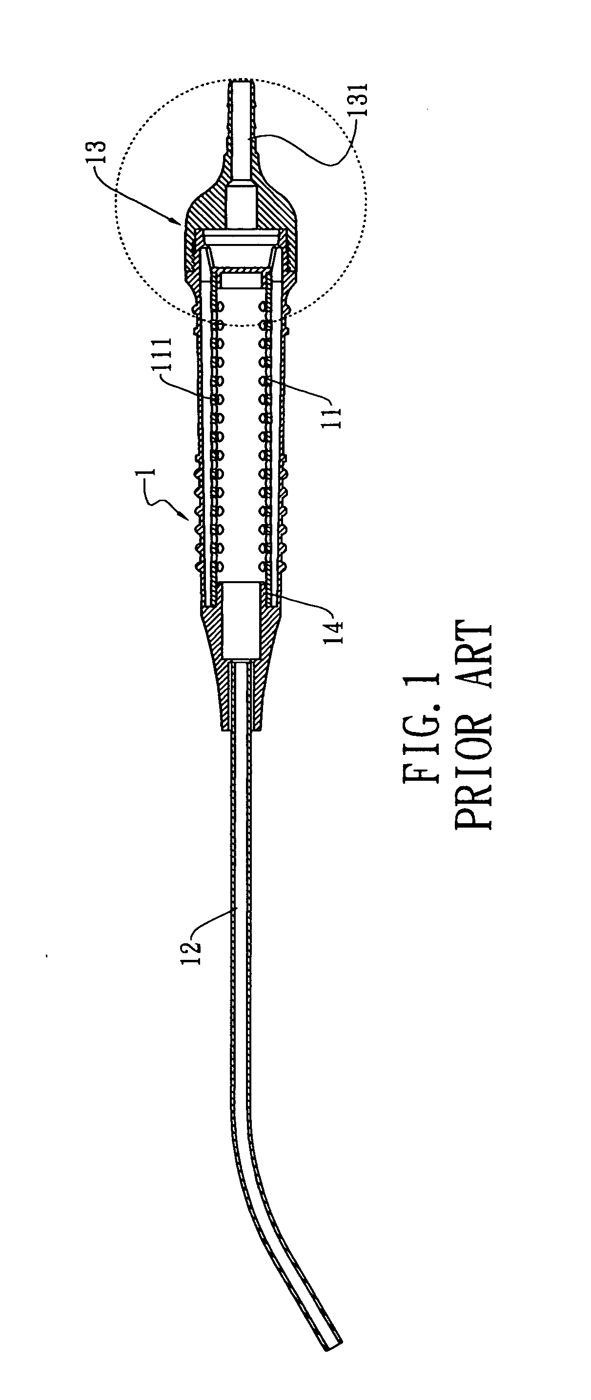
However, because the inner barrel 11 is installed entirely inside the suction handle 1, it is difficult for a medical person to remove the inner barrel 11 from the suction handle 1.
This collecting task is inconvenient for medical personal and further retards the proceeding of the bone surgery.
In sum, the conventional suction set is unable to satisfy medical personals' demand.

Method used


Image

  • Suction set structure for bone surgery
  • Suction set structure for bone surgery
  • Suction set structure for bone surgery

Examples


Embodiment Construction

[0016] Reference will now be made in detail to the preferred embodiments of the present invention, examples of which are illustrated in the accompanying drawings. Wherever possible, the same reference numbers are used in the drawings and the description to refer to the same or like parts.

[0017] Referring to FIG. 3 and FIG. 4, a perspective view and an exploded view of the present invention are shown respectively. The suction set structure for bone surgery of the present invention includes a suction handle 2, a suction tip 23, an inner barrel 3 with a fixing mount 4, and a rear cap 24 with a connecting tube 241. The present invention facilitates the removal and the installation of the inner barrel 3 in the suction handle 2 of the suction set. The chip bone collected inside the inner barrel 3 will not slip out during the removal of the inner barrel 3. Further, the inner barrel 3 is capable of standing upright after removal.

[0018] The suction handle 2 has a front open end 21 and a re...


PUM


Abstract

A suction set structure for bone surgery, which facilitates the removal and installation of an inner barrel, includes a suction handle, a suction tip, a fixing mount engaged with the inner barrel, and a rear cap. The suction tip connects to the inner barrel installed inside the suction handle. The inner barrel has a plurality of apertures which permit blood and bone dust to pass through and enter into the connecting tube of the rear cap while the larger bone chip is collected inside the inner barrel. The fixing mount includes a ring portion, a connecting portion, and a rib flange extending from the ring portion. The rib flange will be located between the rear open end of the suction handle and the rear cap. Such that, the chip bone collected inside the inner barrel will not slip out during the removal of the inner barrel. The removed inner barrel is also capable of standing upright by the fixing mount.

Description

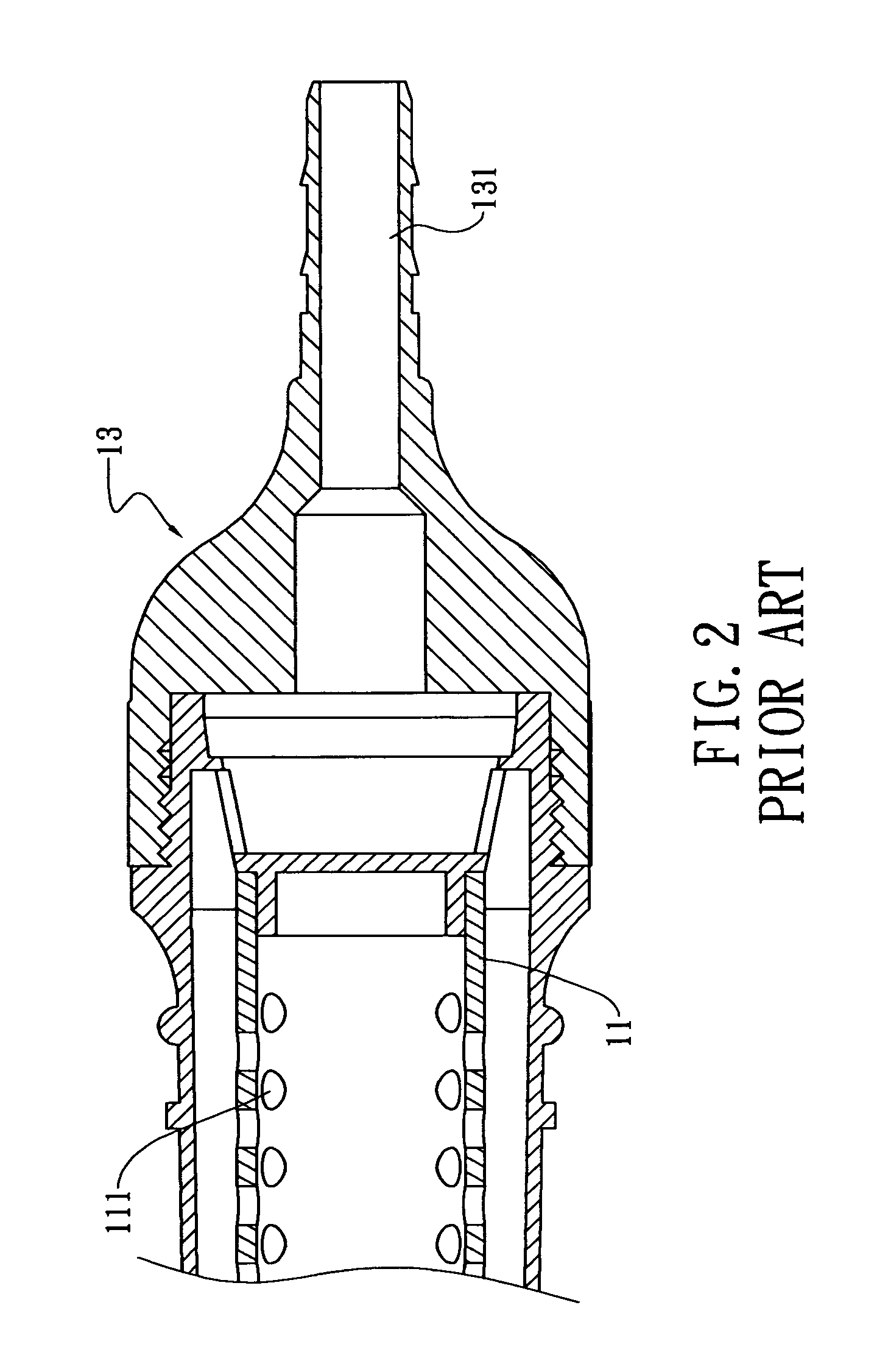
BACKGROUND OF THE INVENTION [0001] The present invention relates in general to a suction set structure for bone surgery, and more particularly, to a structure which enables medical personal to easily remove or install an inner barrel in a suction handle of the suction set. Detaching of the inner barrel will not result in falling of the bone chip collected. Further, the inner barrel is capable of standing upright rather than tilting down. [0002] As illustrated in FIG. 1 and FIG. 2, a conventional suction set for bone surgery includes a suction handle 1, an inner barrel 11, a suction tip 12, and a set of connector 13 and connecting tube 131. One end of the suction handle 1 connects to the suction tip 12 while the other end of the suction handle 1 connects to the connector 13. The inner barrel 11, at both ends thereof having an opening, is installed inside the suction handle 1. The inner barrel 11 has a plurality of apertures which allow liquid or tiny particles to pass through. One of...

Claims


Application Information

Patent Timeline
Patent Type & Authority Applications(United States)
IPC IPC(8): B01F13/06
CPCA61B10/0283A61B10/025
Inventor LEE, GEORGE
Owner PACIFIC HOSPITAL SUPPLY
Why Eureka
Eureka Blog
Learn More