Label conveying apparatus and label printer having the same

a conveying apparatus and label technology, applied in the direction of printing presses, rotary presses, printing presses, etc., can solve the problems of increasing the size and weight increasing the power consumption, and reducing the service life of the conveying apparatus, so as to suppress the error of peeling or jamming of the adhesive label

Inactive Publication Date: 2006-03-16
SEIKO INSTR INC
View PDF11 Cites 15 Cited by
  • Summary
  • Abstract
  • Description
  • Claims
  • Application Information

AI Technical Summary

Benefits of technology

[0020] According to the present invention, the occurrence of slack in the continuous label sheet can be suppressed to enable

Problems solved by technology

In the case where the platen roller and the peeling paper conveying roller are individually driven by independent drive means (such as a motor), two conveyor drive means exist within the label printer, resulting in increases in the size and weight of the apparatus and an increase in its power consumption.
When slack thus develops in the peeling paper 104b, the peeling paper 104b cannot be deflected at a predetermined angle within the peeling mechanism, whereby it becomes diff

Method used


Image

  • Label conveying apparatus and label printer having the same
  • Label conveying apparatus and label printer having the same
  • Label conveying apparatus and label printer having the same

Examples


first embodiment

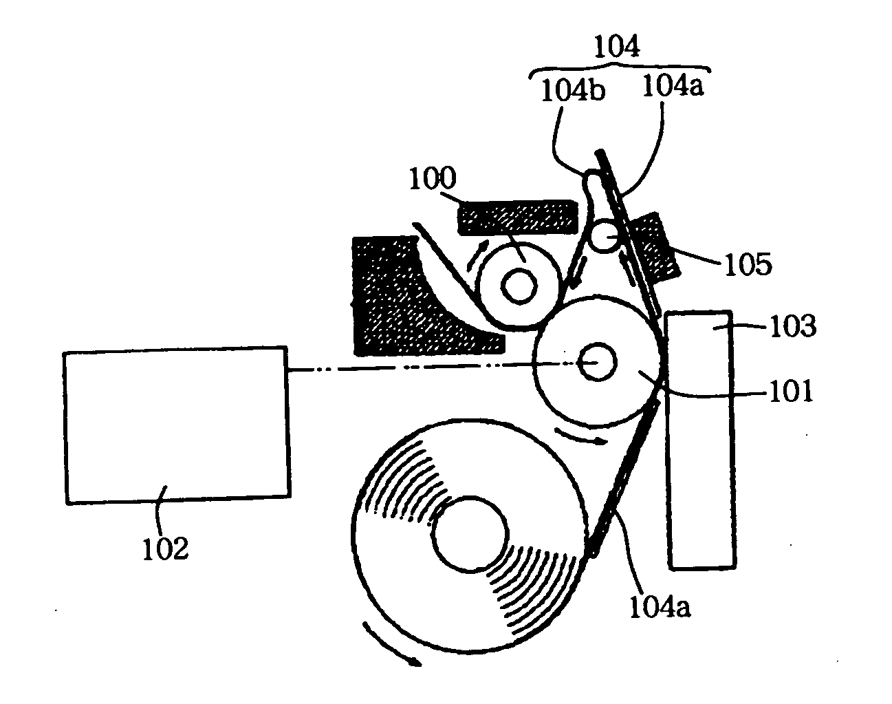
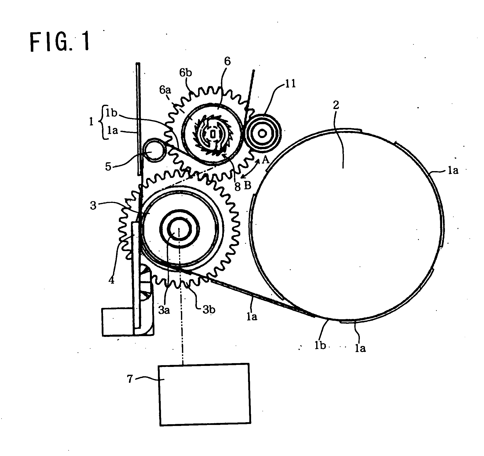
[0027]FIG. 1 is a schematic main portion view of the inner portion of a casing (not shown) of a label printer having a label conveying apparatus according to a first embodiment of the present invention. Now, the basic construction of the label printer is described. The label printer includes, inside the casing (not shown): a holding portion for a roll member 2 around which a continuous label sheet 1 is wound; a platen roller 3 for successively drawing out the continuous sheet 1 from the roll member 2; a thermal head 4 opposed in close proximity to the platen roller 3, for recording letters, numbers, symbols, and the like on a non-adhesive surface of an adhesive label 1a of the continuous label sheet 1; a small-diameter peeler bar (peeling mechanism) 5 for deflecting the continuous label sheet 1 having passed the gap between the platen roller 3 and the thermal head 4 to thereby peel off the adhesive label 1a that has undergone recording from a peeling paper 1b ; a peeling paper conve...

second embodiment

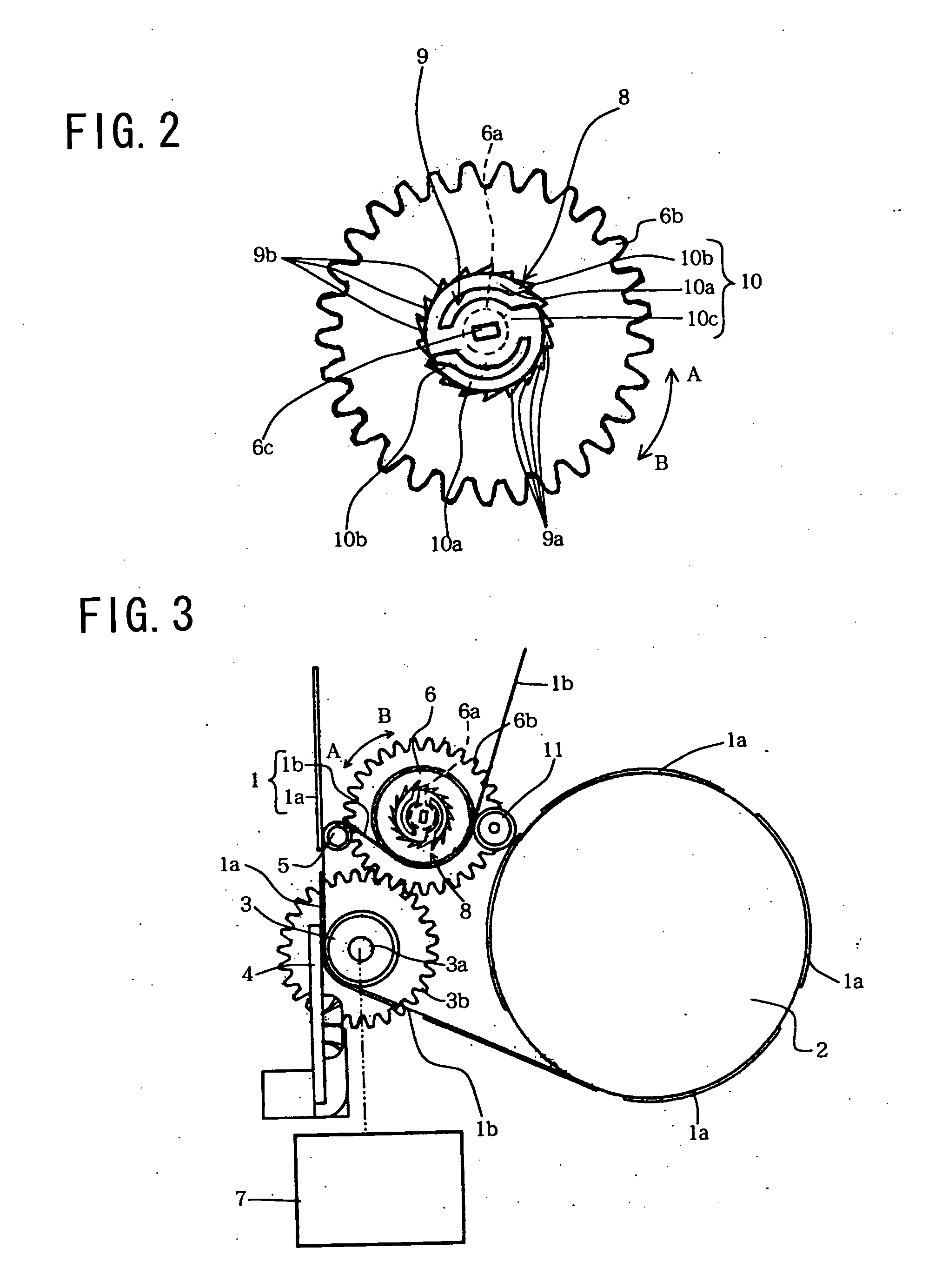
[0045] Next, a second embodiment of the present invention is described with reference to FIG. 3. It should be noted that the portions identical to those of the first embodiment are denoted by the same reference symbols and detailed description thereof is omitted.

[0046] In a label printer having a label conveying apparatus according to this embodiment, the platen roller driving gear 3b and the conveying roller driving gear 6b are of the same size and configuration; instead, the peeling paper conveying roller 6 is larger in diameter than the platen roller 3.

[0047] In the first embodiment, the conveying roller driving gear 6b is smaller in diameter than the platen roller driving gear 3b and the rpm of the peeling paper conveying roller 6 is larger than that of the platen roller 3, whereby the conveying capacity of the peeling paper conveying roller 6 becomes large. According to this embodiment, in contrast, while the conveying roller driving gear 6b is of the same diameter as the pla...


PUM


Abstract

A motor (7) rotates a platen roller (3) so as to convey a continuous label sheet (1) drawn out from a roll member (2). A thermal head (4) generates heat at an appropriate timing in synchronism with the conveyance, thereby effecting recording on an adhesive label (1). The continuous label sheet (1) that has undergone recording is deflected along the outer periphery of a peeler bar (5), causing an adhesive label (1a) to peel off from a peeling paper (1b). The peeling paper (1b) from which the adhesive label (1a) has been peeled off reaches the outer periphery of a peeling paper conveying roller (6). Torque is transmitted via an accelerating wheel train composed of a platen roller driving gear (3b) and a conveying roller driving gear (6b), whereby the peeling paper conveying roller (6) conveys the peeling paper (1b) at a greater conveying capacity than the platen roller (3). The continuous label sheet (1) (peeling paper (1b)) advances while being constantly applied with a force pulling it from the leading edge side (downstream side), whereby no slack develops in the continuous label sheet (1) as it is conveyed.

Description

BACKGROUND OF THE INVENTION [0001] 1. Field of the Invention [0002] The present invention relates to a label conveying apparatus for manufacturing an adhesive label and to a label printer having the label conveying apparatus. [0003] 2. Description of the Related Art [0004] Adhesive labels having desired letters, numbers, symbols, and the like printed on their non-adhesive surface are conventionally used in order, for example, to indicate the price, name, and the like of each merchandise item in stores or to indicate the type and the like of items stored in warehouses. Adhesive labels of this type are manufactured by using label printers, with which a plurality of adhesive labels are temporarily adhered to a single peeling paper to prepare a continuous label sheet, and after the continuous label sheet is conveyed to a recording head and printing is effected on the non-adhesive surface of each adhesive label, the adhesive labels are peeled off from the peeling paper by a peeling mecha...

Claims


Application Information

Patent Timeline
IPC IPC(8): B41F15/04
CPCB41J15/005
Inventor ITAKURA, TOSHIHARU
Owner SEIKO INSTR INC
Why Eureka
Try Eureka