

A milling tool with cooperating projections and recesses between the cutting insert and the holder
a technology of projections and recesses, which is applied in the direction of milling cutters, milling equipment, transportation and packaging, etc., can solve the problems of difficult to precisely position the cutting insert on the tool body and clamp the same rigidly, and the use of the end mill is complicated and severe. achieve the effect of precise positioning of the cutting inser
- Summary
- Abstract
- Description
- Claims
- Application Information
AI Technical Summary
Benefits of technology
Problems solved by technology
Method used
Image

Examples
Embodiment Construction
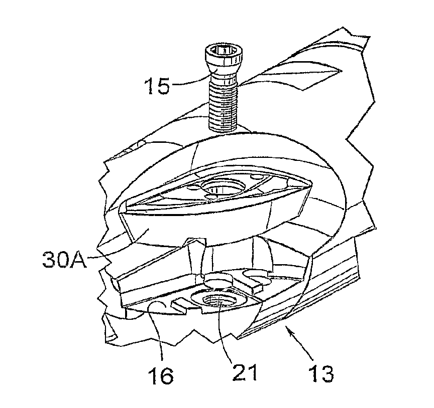
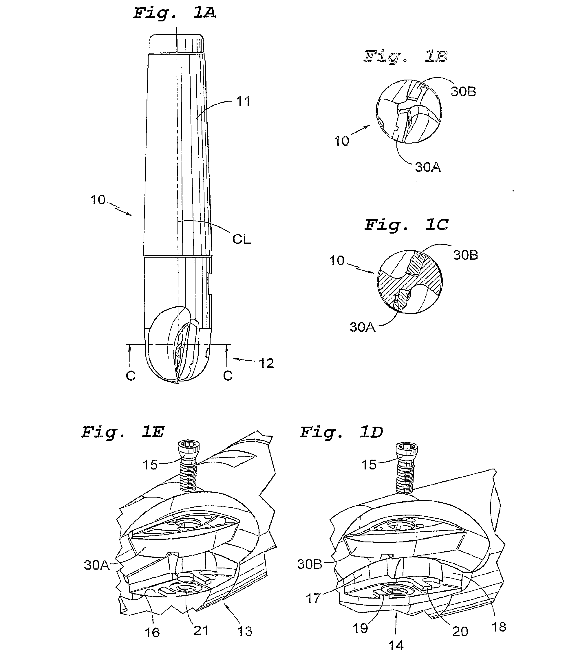
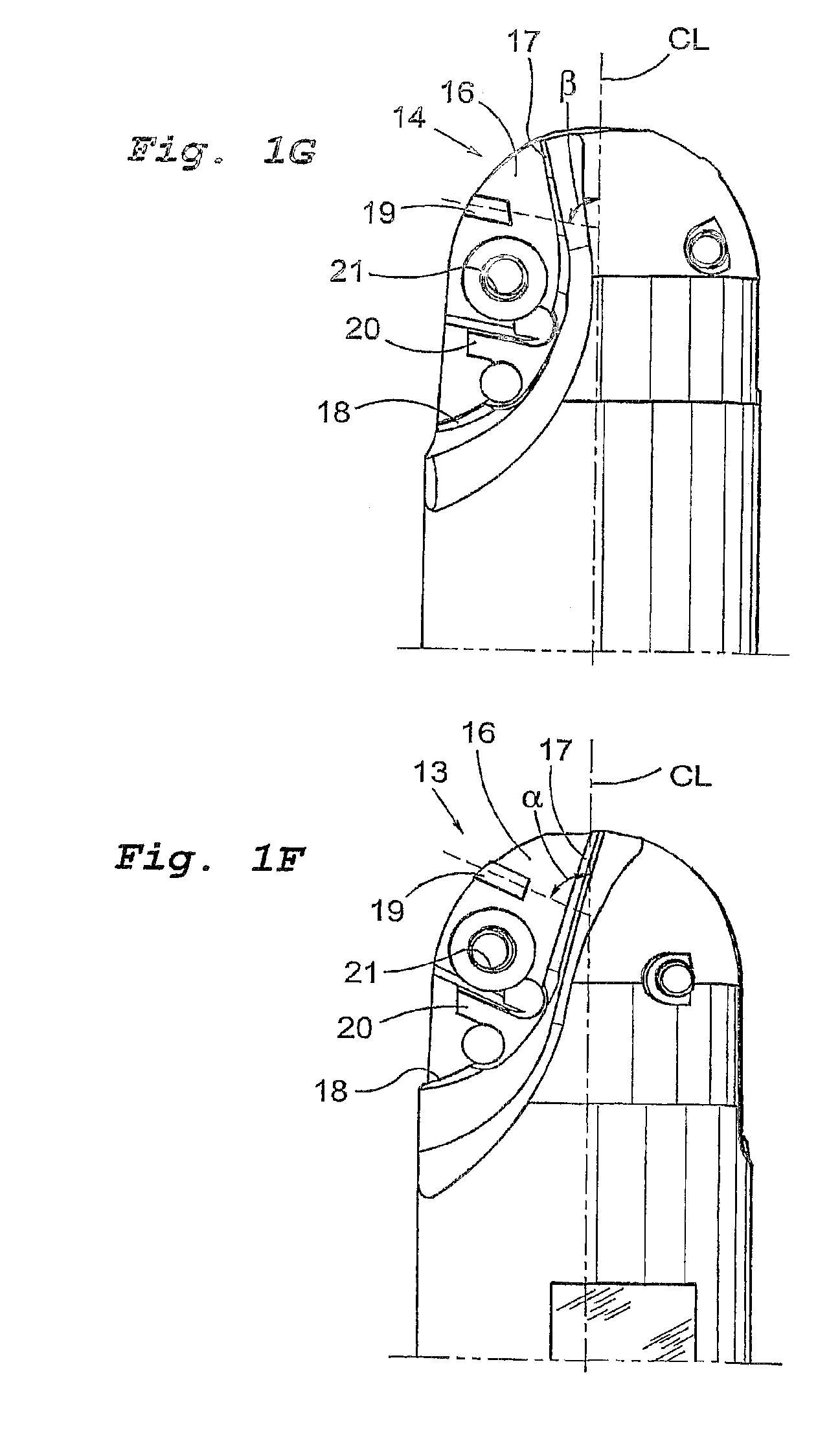
[0012] In FIGS. 1A-1E, a milling tool 10 is shown according to the present invention, intended to machine foremost moulding tools for the moulding industry.
[0013] The milling tool has a holder having a shaft 11 and a front chip-removing end 12.
[0014] The end 12 has two cutting insert pockets 13, 14, each carrying a cutting insert 30, preferably made from sintered cemented carbide. A clamping means or a screw 15 holds the cutting insert in the cutting insert pocket. The cutting inserts 30A, 30B are so placed that one of the cutting inserts or the interior cutting insert 30A in the interior cutting insert pocket 13 extends in to and preferably past the centre line CL of the tool. This means that the tool can bore in the workpiece. The second cutting insert or the exterior cutting insert 30B in the exterior cutting insert pocket 14 is arranged somewhat at the side of the centre line CL. The active cutting edges of the cutting inserts are arranged so that they forma perfect semi-spher...
PUM
| Property | Measurement | Unit |
|---|---|---|
| Fraction | aaaaa | aaaaa |
| Fraction | aaaaa | aaaaa |
| Length | aaaaa | aaaaa |
Abstract
Description
Claims
Application Information