Motor-pump unit

a technology of motor-pump units and roller bearings, which is applied in the direction of positive displacement liquid engines, piston pumps, liquid fuel engines, etc., can solve the problems of reducing the affecting the service life of the pump, and premature failure of the bearings, so as to reduce the risk of bearing damage and the washout of lubricants from the bearings.

Inactive Publication Date: 2006-03-16
CONTINENTAL TEVES AG & CO OHG
View PDF5 Cites 13 Cited by
  • Summary
  • Abstract
  • Description
  • Claims
  • Application Information

AI Technical Summary

Benefits of technology

[0004] An object of the invention is to provide an improved motor-pump unit where the risk of bearing damages and the washout of lubricants from bearings is reduced.
[0005] According to the invention, this object is achieved because the bearing separates the chamber from the free space, and because a connection is provided between the chamber and the free space which acts quasi as a bypass circumventing the interior of the roller bearing so that it neither must be feared that lubricants are washed out, nor that sealing means are damaged. The result is that sealed roller bearings can be used, which are protected against washouts of lubricants. A quick and, hence, low-cost pressure fluid filling process is rendered possible nevertheless.
[0011] According to the invention, the bearing is arranged in a stepped through-hole of the accommodating member, with the bearing adjoining the free space, and the through-hole and the free space being provided with a closure means. Manufacturing a through-hole is simple compared to manufacturing a blind-end bore and, in addition, allows supporting the shaft end when mounting a bearing close to the motor.
[0012] The closure means is preferably designed as a cover that abuts on a bore step, with said cover being calked with the accommodating member. The cover can be a deepdrawn or molded part, and the calking at the housing also reduces the costs of manufacture. Principally, a tool-free clinching engagement between the cover and the accommodating member is possible without departing from the spirit of the invention. In this respect, provision must be made to ensure that the cover includes an appropriate profiling and is made of a harder material than the accommodating member.
[0014] A favorable design of the embodiment disposes of a channel provided in the accommodating member. The leakage volume that can be received is further increased because the channel opens into a chamber that is delimited by the end plate and the accommodating member, said chamber being connected to the leakage discharge channel.

Problems solved by technology

It has shown that roller bearing assemblies of motor-pump units are exposed to high stress, which is untypical of roller bearings, in particular during the pressure fluid filling process.
This fact, in turn, can cause lubricants to be washed out and, consequently, can lead to a reduced lifetime of the pump.
The bearings will fail prematurely what is problematic in particular in brake systems with long pump operating times as is the case in electrohydraulic brake systems in particular.
Bearings, which are not sealed, provide a free access to the roller surfaces and do not allow using a special lubricant.
This entails problems when the lubricating properties of the pressure fluid used are not appropriate, or when the pressure fluid contains wear particles that can cause damage to the running surfaces.

Method used


Image

  • Motor-pump unit
  • Motor-pump unit
  • Motor-pump unit

Examples


Embodiment Construction

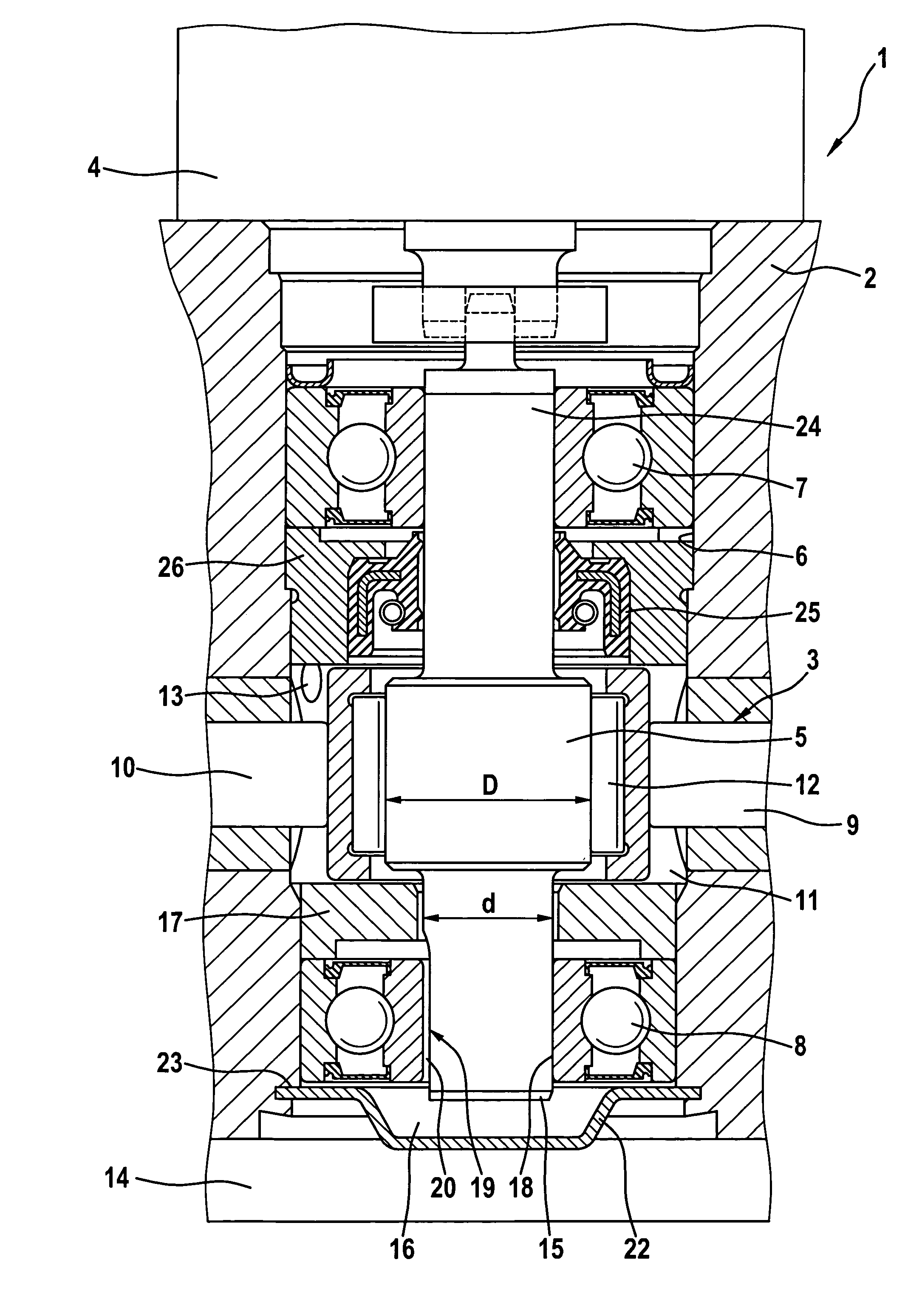
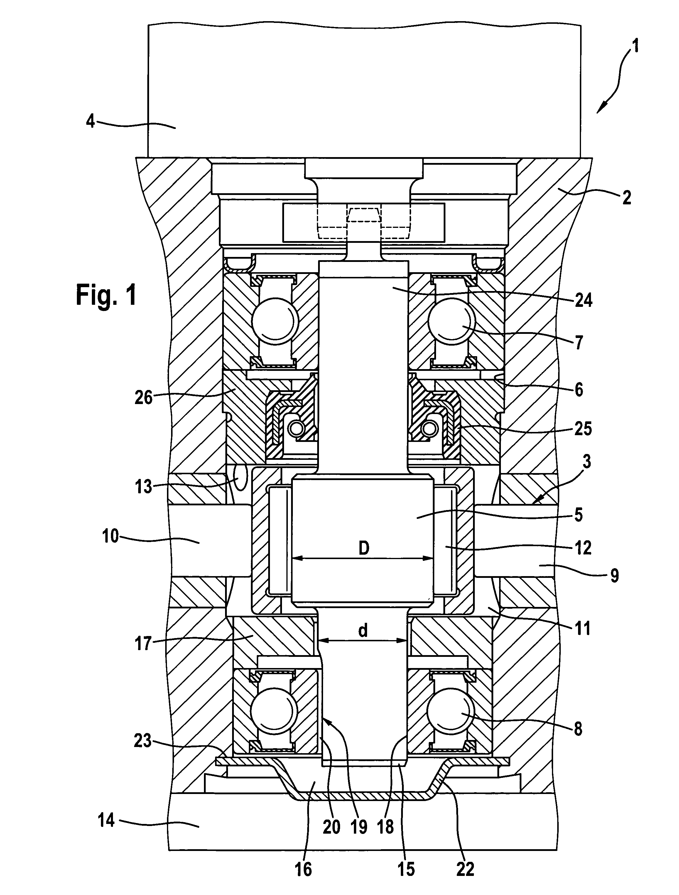
[0018] A motor-pump unit 1 for application in a motor vehicle brake system is connected to wheel brakes (not shown), on the one hand, and to a generator (not shown) such as a master brake cylinder with a pressure fluid supply tank, on the other hand. An accommodating member 2 comprises at least six hydraulic connections for this purpose. The unit is especially appropriate and destined for electrohydraulic brake systems being equipped with a high-pressure accumulator integrated at or in the accommodating member 2 and used to feed the wheel brakes. In this arrangement, the master brake cylinder is only used for the braking operation in a case of emergency and primarily serves for the simulation of brake application forces.

[0019] The motor-pump unit 1 further comprises a pump 3 for feeding the high-pressure accumulator or for feeding wheel brakes and a motor 4 for driving the pump 3. An electronic unit 14 for controlling and regulating the system is positioned on a side of the accommo...


PUM


Abstract

The invention relates to a motor-pump unit for a motor vehicle brake system, comprising a motor and a pump which is provided with a shaft that is driven by said motor, with the shaft end being rotatably mounted by means of at least one bearing in an accommodating member having valves and connecting channels, said shaft driving displacement means which are disposed in a chamber that can be filled with pressure fluid. In order to improve vacuum filling of the brake system with pressure fluid, the invention discloses that the shaft end terminates into a free space, and that at least one connection is provided between the free space and the chamber.

Description

TECHNICAL FIELD [0001] The present invention relates to a motor-pump unit for a motor vehicle brake system, comprising a motor and a pump which is provided with a shaft that is driven by said motor, with the shaft end being rotatably mounted by means of at least one bearing in an accommodating member having valves and connecting channels, said shaft driving displacement means which are disposed at least in part in a chamber that can be filled with pressure fluid and in which the bearing runs at least in part, and with the shaft end terminating into a free space. BACKGROUND OF THE INVENTION [0002] A motor-pump unit of this type is disclosed in DE 199 27 658 A1. In general, a motor vehicle brake system is filled with the necessary pressure fluid after the assembly of the individual system components such as in particular a master brake cylinder, a tube and hose line system, the motor-pump unit and wheel brakes at the vehicle manufacturer's premises. For this purpose, the entire brake ...

Claims


Application Information

Patent Timeline
Patent Type & Authority Applications(United States)
IPC IPC(8): F04B17/00F04B35/04F04B1/04F04B17/03F04B53/00
CPCB60T8/368B60T8/4031F04B1/04F04B53/006F04B1/0443F04B17/03F04B1/0404
Inventor DINKEL, DIETERBARTSCH, THOMASMARTIN, SVENBRIESEWITZ, RIIDIGERNIESCHER, AXEL
Owner CONTINENTAL TEVES AG & CO OHG
Why Eureka
Try Eureka