
Insulation displacement system for two electrical conductors

Inactive Publication Date: 2006-03-16
3M INNOVATIVE PROPERTIES CO
View PDF49 Cites 18 Cited by
  • Summary
  • Abstract
  • Description
  • Claims
  • Application Information

AI Technical Summary

Benefits of technology

[0005] The present invention provides an electrically coupled insulation displacement system. The electrically coupled insulation displacement system comprises a first contact and a second contact. The first contact includes a first insulation displacement slot therein having an open end and a closed end. The first insulation displacement slot has a first portion having a width adjacent the open end and a second portion having a width intermediate th

Problems solved by technology

However, when the IDC element has a single, uniform slot, a greater force is required to insert the second wire because the first wire encounters significant resistance when inserted further into the slot.
Additionally, when the first wire is inserted further into the slot, undesirable bending outward of the IDC element may occur.
The outward bending may interfere with making a proper connection between the IDC element and second electrical conductor.

Method used


Image

  • Insulation displacement system for two electrical conductors
  • Insulation displacement system for two electrical conductors
  • Insulation displacement system for two electrical conductors

Examples


Embodiment Construction

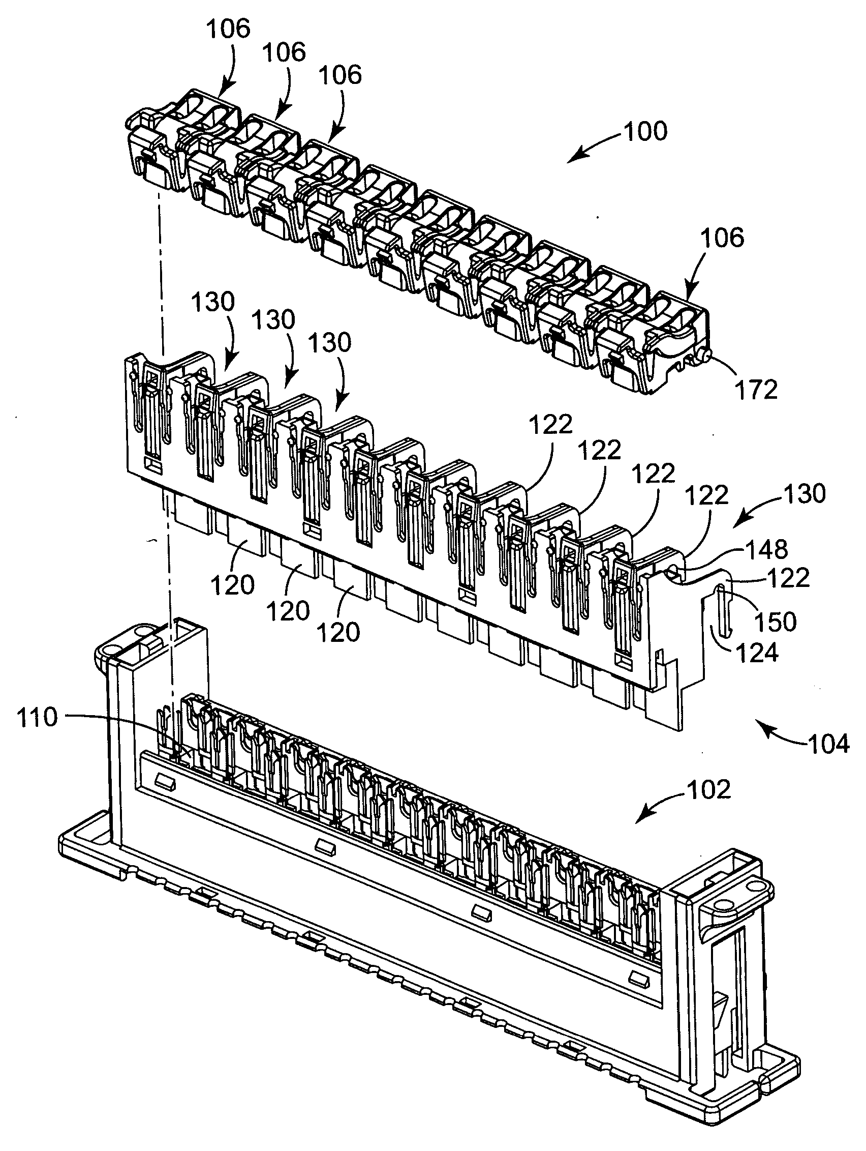
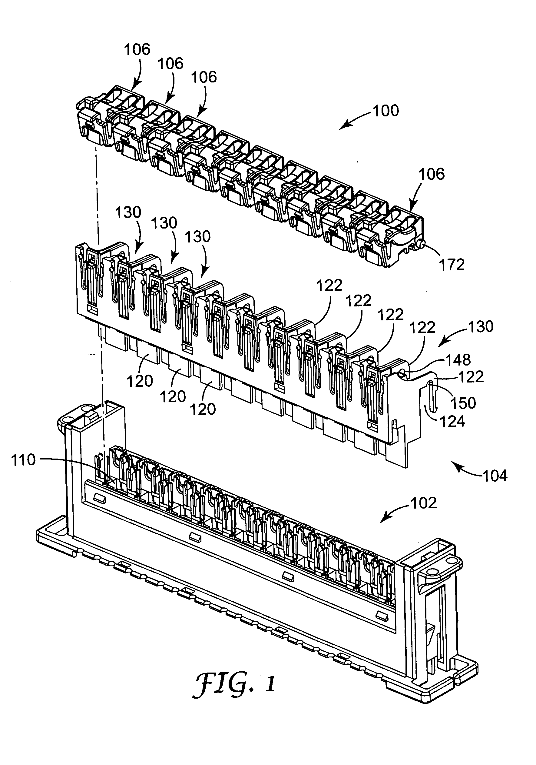
[0020]FIG. 1 is an exploded perspective view of an IDC connector assembly 100 of the present invention. The connector assembly 100 comprises a base unit 102, a connector unit 104, and a plurality of caps 106. In FIG. 1, the connector assembly 100 is shown disassembled. To assemble the connector assembly 100, the caps 106 are inserted in between lock projections 122 projecting from a rear side of the connector unit 104 and then the connector unit 104 is placed over and slid into the base unit 102.

[0021] The base unit 102 comprises an insulated housing with a series of receiving slots 110 for connection with the connector unit 104. Lock slots on a rear side of the base unit 102 receive lock projections 122 of the connector unit 104 to lock the connector unit 104 to the base unit 102.

[0022] Located within the base unit 102 are a plurality of electrical elements 114 (see FIG. 11 and FIG. 12). Each electrical element 114 is in the form of an IDC element, and is adapted to make electric...


PUM


Abstract

An electrically coupled insulation displacement system comprises a first contact having a first insulation displacement slot therein having an open end and a closed end. The first insulation displacement slot has a first portion having a width adjacent the open end and a second portion having a width intermediate the first portion and the closed end, the first portion has a larger width than the second portion. The insulation displacement system further comprises a second contact, which includes a second insulation displacement slot therein having an open end and a closed end. The second insulation displacement slot has a first portion having a width adjacent the open end and a second portion having a width intermediate the first portion and the closed end, the first portion has a smaller width than the second portion.

Description

FIELD [0001] The present invention relates to electrical contacts. In one particular aspect, the present invention relates to an insulation displacement element within a connector assembly for use in making an electrical connection with an electrical element. BACKGROUND [0002] In a telecommunications context, connector blocks are connected to cables that feed subscribers while other connector blocks are connected to cables to the central office. To make the electrical connection between the subscriber block and the central office block, jumper wires are inserted to complete the electrical circuit. Typically jumper wires can be connected, disconnected, and reconnected several times as the consumer's needs change. [0003] An insulation displacement connector, or IDC, element is used to make the electrical connection to a wire or electrical conductor. The IDC element displaces the insulation from a portion of the electrical conductor when the electrical conductor is inserted into a slot...

Claims


Application Information

Patent Timeline
IPC IPC(8): H01R4/24
CPCH01R4/2433H01R11/05H01R4/2454
Inventor FASCE, XAVIERMETRAL, GUYPRATT, JEROME A.
Owner 3M INNOVATIVE PROPERTIES CO
Learn More