Method for determining driving task demand based on speed variability

a technology of speed variability and task demand, applied in the direction of reradiation, pedestrian/occupant safety arrangement, instruments, etc., can solve the problems of increasing the driving task demand of the driver, requiring more attention, and conventional infotainment control systems and collision warning systems generally do not provide dynamic control of various features

Active Publication Date: 2006-03-16
APTIV TECH LTD
View PDF10 Cites 9 Cited by
  • Summary
  • Abstract
  • Description
  • Claims
  • Application Information

AI Technical Summary

Benefits of technology

[0006] The present invention provides for a system and method of assessing the driving task demand on the driver of a vehicle, and further controls one or more devices on the vehicle as a function of the assessed driving task demand. According to one aspect of the present invention, the method includes the steps of sensing a coverage zone in relation to a vehicle, determining a presence of one or more objects in the sensed zone, and measuring speed of each detected object in the sensed zone. The method also includes the steps of determining a variation in speed of one or more sensed objects and determining a driving task demand signal indicative of driving task demand as a function of the measured speed variability. According to a further aspect of the present invention, the method may control one or more devices on the vehicle based on the assessed driving task demand signal.

Problems solved by technology

Conversely, when driving on a multi-lane winding road with erratic traffic, the driver is subjected to a higher driving task demand that requires more attention.
Conventional infotainment control systems and collision warning systems generally do not provide dynamic control of various features on a vehicle to permit the driver to engage distracting features in low traffic on straight roads, and to shield the driver against excessive distraction when driving in higher risk situations.

Method used


Image

  • Method for determining driving task demand based on speed variability
  • Method for determining driving task demand based on speed variability
  • Method for determining driving task demand based on speed variability

Examples


first embodiment

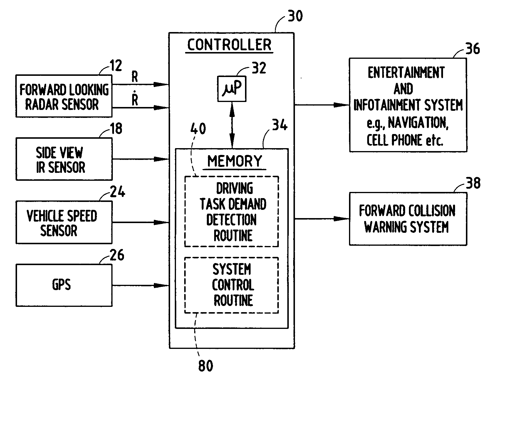
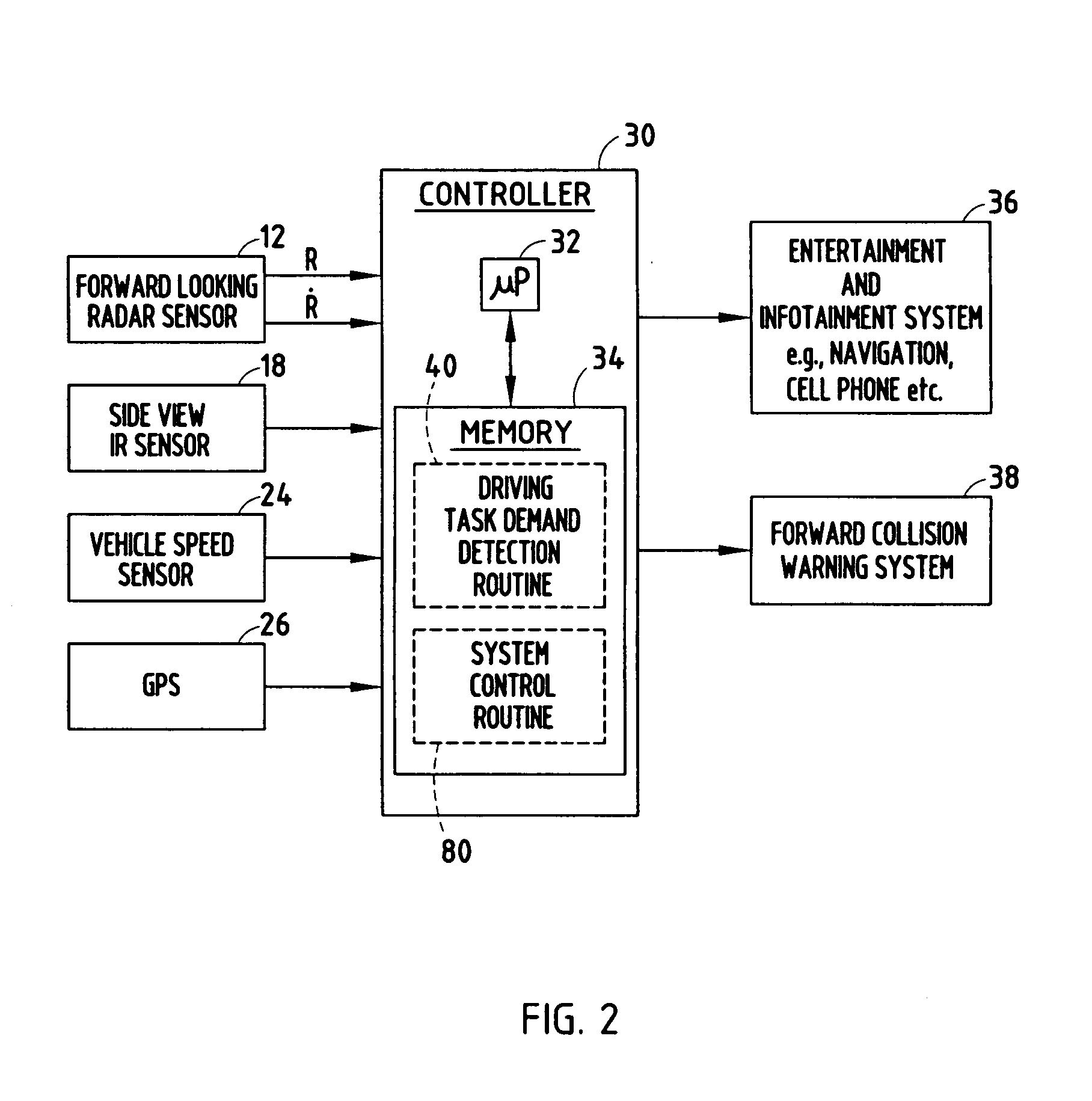
[0027] Referring to FIG. 3, the driving task demand detection routine 40 is illustrated which employs the forward looking radar sensing system and the side view IR sensing system. Routine 40 begins at step 42 and performs an initialization in step 44. The initialization may include setting the total number of forward targets N equal to zero, setting the number of frames per target ni equal to zero, setting the number of frames within a time window T, and may include other initial settings.

[0028] Following the initialization step 44, routine 40 proceeds to step 46 to obtain and store ranger Ri, range rate {dot over (R)}i for each of the detected forward target objects i, the side vehicle information (30), and the host vehicle information Vh for frame j. Frame j includes the sensed data at a particular time captured in frame j. Next, routine 40 calculates the total number of detected forward targets N, the number of frames per target ni, and the speed for each detected forward target...

second embodiment

[0038] Referring to FIG. 5, a driving task demand detection routine 140 is illustrated absent the use of the forward looking radar system and the side view object detection system. Instead of sensing objects forward or to the side of the host vehicle, routine 140 determines the driving task demand signal Demandj based on speed of the host vehicle 10.

[0039] Routine 140 begins at step 142 and performs an initialization in step 144. The initialization includes setting the number of frames for the host vehicle nh equal to zero and setting the number of frames within a time window T. Next, in step 146, routine 140 obtains and stores the host vehicle speed Vh for frame j in step 146. In step 148, routine 140 calculates the number of frames for the host vehicle nh.

[0040] Proceeding to decision step 150, routine 140 determines if the number of frames for the host vehicle nh is greater than one and, if not, sets a speed variance Sh2 equal to zero in step 152. Routine 140 then computes the ...


PUM


Abstract

A system and method of assessing the driving task demand on the driver of a vehicle, and further controlling one or more devices on the vehicle as a function of the assessed driver demand is provided. The method includes sensing a coverage zone in relation to a vehicle, determining a presence of one or more objects in the sensed zone, measuring speed of each detected object in the sensed zone, determining a variation in speed of one or more sensed objects, and determining a driving task demand signal indicative of driving task demand of the vehicle as a function of the measured speed variability. The method controls one or more devices on the vehicle based on the driving task demand signal. Alternately, the driving task demand signal is determined based on vehicle speed.

Description

TECHNICAL FIELD [0001] The present invention generally relates to object detection and driver distraction systems on a vehicle and, more particularly, relates to a system and method of determining driving task demand for a vehicle driver. BACKGROUND OF THE INVENTION [0002] Automotive vehicles are increasingly equipped with various electronic entertainment and information systems and mobile multimedia devices, generally referred to herein as infotainment devices and systems. For example, automotive personal computing (PC) devices have been installed in vehicles to allow personal computing, web browsing, accessing e-mail, and other Internet access. Additionally, many vehicles are equipped with navigation systems, televisions, and video game systems. These and other infotainment systems typically include a human machine interface (HMI) for enabling a user to interface with the system. The HMI typically includes a display for viewing messages, navigational maps, video images, audio feat...

Claims


Application Information

Patent Timeline
Patent Type & Authority Applications(United States)
IPC IPC(8): B60T7/12
CPCB60R16/0232G01C21/26B60R21/0134
Inventor SMITH, MATTHEW R.ZHANG, HARRYSCHARENBROCH, GREGORY K.WITT, GERALD J.NEWMAN, TIMOTHY J.
Owner APTIV TECH LTD
Why Eureka
Try Eureka