Cyclone dust collecting apparatus

a dust collecting apparatus and cyclone technology, applied in the field of vacuum cleaners, can solve the problems that the improved vacuum cleaners are not enough to thoroughly collect fine dust, and achieve the effect of effective collection of fine dus

Inactive Publication Date: 2006-03-23
SAMSUNG GWANGJU ELECTRONICS CO LTD
View PDF6 Cites 49 Cited by
  • Summary
  • Abstract
  • Description
  • Claims
  • Application Information

AI Technical Summary

Benefits of technology

[0007] An aspect of the present invention is to solve at least the above problems and / or disadvantages and to provide at least the advantages described below. Accordingly, an aspect of the present invention is to provide a cyclone dust collecting apparatus capable of effectively collecting fine dust.

Problems solved by technology

However, the improved vacuum cleaner is still not enough yet to thoroughly collect fine dust included in the air.

Method used


Image

  • Cyclone dust collecting apparatus
  • Cyclone dust collecting apparatus
  • Cyclone dust collecting apparatus

Examples


Embodiment Construction

[0028] Hereinafter, an embodiment of the present invention will be described in detail with reference to the accompanying drawing figures.

[0029] In the following description, same drawing reference numerals are used for the same elements even in different drawings. The matters defined in the description such as a detailed construction and elements are nothing but the ones provided to assist in a comprehensive understanding of the invention. Thus, it is apparent that the present invention can be carried out without those defined matters. Also, well-known functions or constructions are not described in detail since they would obscure the invention in unnecessary detail.

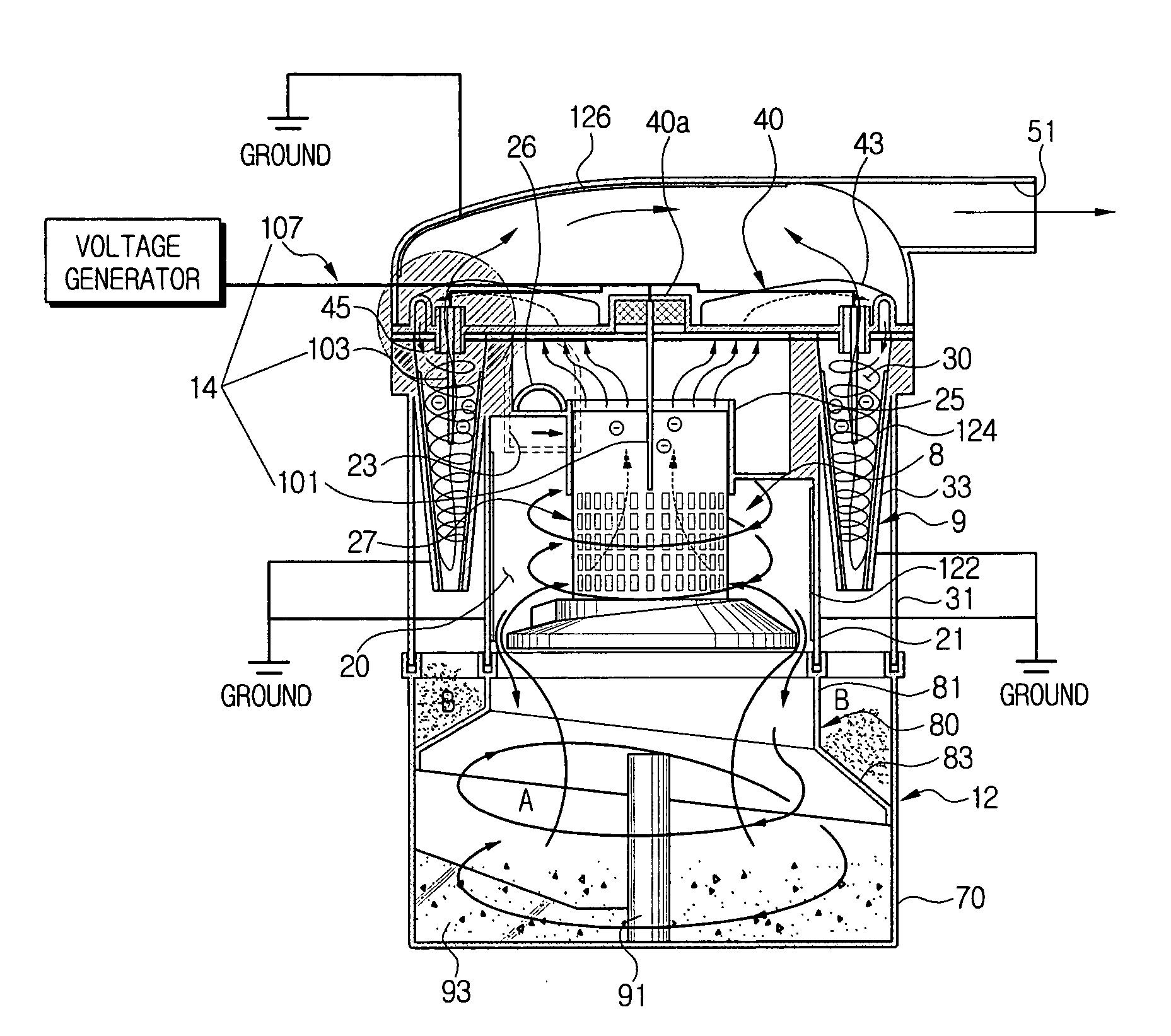
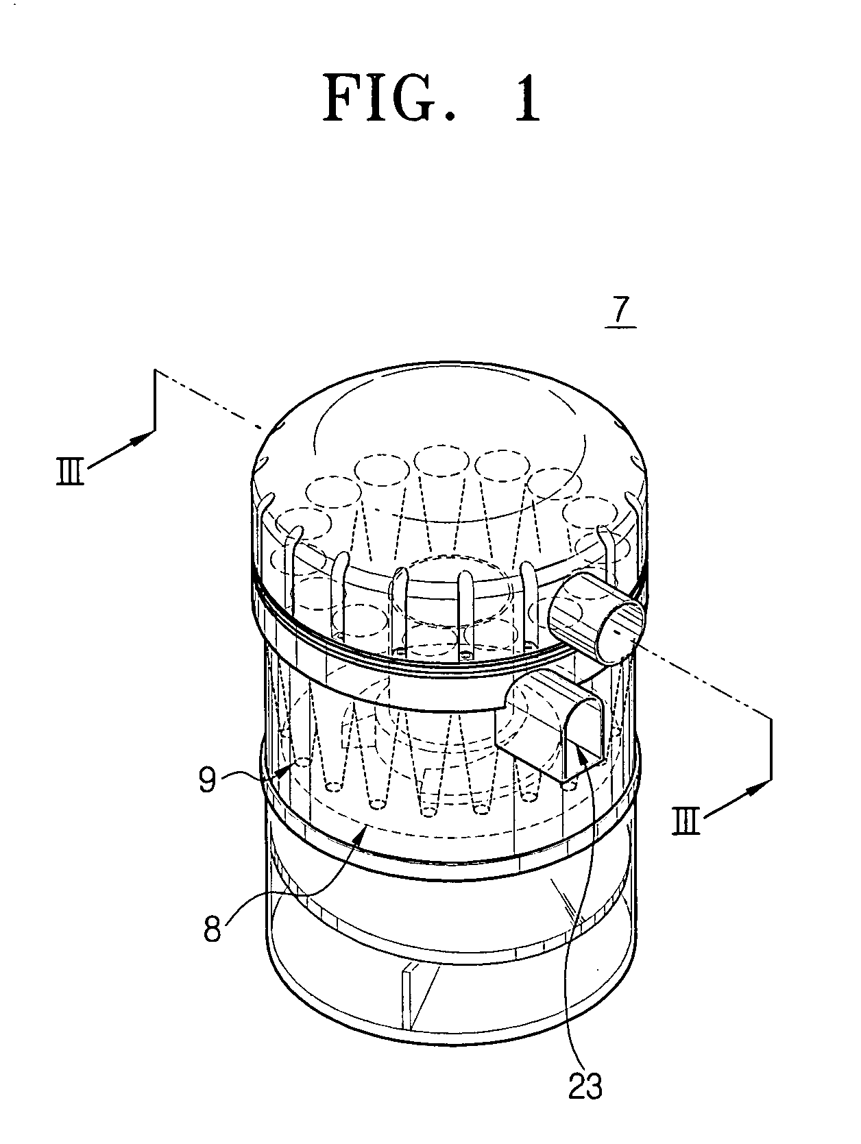
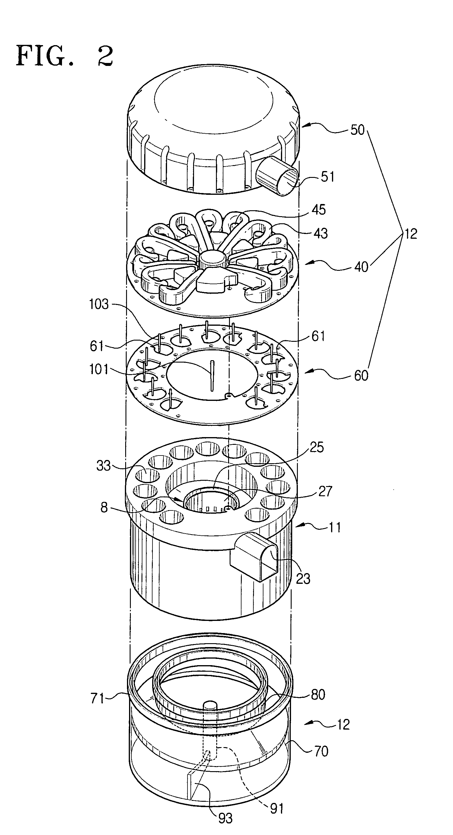
[0030] Referring to FIGS. 1 through 3, a cyclone dust collecting apparatus 7 according to an embodiment of the present invention is constructed by a multi-cyclone unit II comprising a first cyclone 8 and a plurality of second cyclones 9.

[0031] The first cyclone 8 is disposed in a center portion of the multi-cyclone u...


PUM

PropertyMeasurementUnit
conductiveaaaaaaaaaa
voltageaaaaaaaaaa
centrifugal forceaaaaaaaaaa

Abstract

A cyclone dust collecting apparatus comprises a first cyclone for centrifuging dust from drawn-in air; one or more second cyclones for separating dust from air which is passed through the first cyclone; and an electrode unit mounted to at least one of the first and the second cyclones.

Description

CROSS-REFERENCE TO RELATED APPLICATIONS [0001] This application claims the benefit of Korean Patent Application No. 2004-75370, filed Sep. 21, 2004, in the Korean Intellectual Property Office, the disclosure of which is incorporated herein by reference. BACKGROUND OF THE INVENTION [0002] 1. Field of the Invention [0003] The present invention relates to a vacuum cleaner. More particularly, the present invention relates to a cyclone dust collecting apparatus for separating impurities such as dust included in drawn-in air using a centrifugal force and electricity. [0004] 2. Description of the Related Art [0005] A vacuum cleaner generally comprises a suction brush moving along a surface being cleaned and connected to a cleaner body, a dust collecting apparatus detachably mounted in the cleaner body and a motor for supplying a suction force. By the suction force generated by the motor, dust and assorted impurities on the surface being cleaned are drawn into the cleaner body and filtered ...

Claims


Application Information

Patent Timeline
Patent Type & Authority Applications(United States)
IPC IPC(8): B01D45/12A47L9/16B03C3/017B03C3/15B03C3/74B04C5/26B04C9/00
CPCA47L9/16A47L9/1625A47L9/1641B01D45/12B04C2009/001B03C3/15B03C3/74B04C5/26B04C9/00B03C3/017B04C5/24B04C5/28
Inventor HAN, JUNG-GYUNOH, JANG-KEUNSEO, JI-WON
Owner SAMSUNG GWANGJU ELECTRONICS CO LTD
Why Eureka
Try Eureka