Method for changing the lift of an inlet valve of an internal combustion engine

a technology of inlet valve and lift, which is applied in the direction of valve arrangement, combustion engine, machine/engine, etc., can solve the problems of difficult to achieve the effect of reducing suction capacity, difficult to achieve, and relatively great torque jump

Active Publication Date: 2006-03-23
DAIMLER AG
View PDF5 Cites 1 Cited by
  • Summary
  • Abstract
  • Description
  • Claims
  • Application Information

AI Technical Summary

Benefits of technology

[0012] The size of the camshaft phase angle over the rotational speed and the load of the internal combustion engine when using the partial lift cams or the full lift cams is stored in a characteristic performance graph within a control device of the internal combustion engine. The dynamic changeover described between the full lift cams and the partial lift cams takes place then by the control device going back to the stored characteristic performance graph values or to the characteristics stored therein and bringing about the mechanical changeover. For this, it is advantageously not necessary to change the position of the throttle valve, that is to carry out temporal precontrol by means of the throttle valve, so that the method according to the invention can be carried out with considerably less outlay than methods known from the prior art. In this connection, it is possible to adjust the lift and the control times of the inlet valves independently of one another, whereby the method according to the invention is made possible in the first place.
[0013] The correspondence of the suction capacity of the internal combustion engine can be achieved in an especially simple and advantageous way when using the full lift inlet cam profiles described by shifting the closing time of the inlet valves toward late inlet valve closing. The adjustment of the closing time of the inlet valves toward late inlet closing, leads to a lower suction capacity of the internal combustion engine operated with the full lift cams as the air taken in is to a certain extent pushed out of the cylinders again before the inlet valves close. With corresponding design of the partial lift cams in relation to the full lift cams with the consequence of a greater percentage of the fresh air taken in remaining when the partial lift cam is used, correspondence of the suction capacity concerned can thus be achieved.

Problems solved by technology

In this connection, however, it is problematic that, when changing over between the partial lift and the full lift of the inlet valves, a relatively great torque jump occurs because of the much greater cylinder filling via the increased inlet valve flow cross-section which the driver may experience as unpleasant.
Changing the throttle valve angle in particular, and consequently the adaptation of the fresh air mass flow into the internal combustion engine, is a very problematic and complex operation, however, which moreover cannot be carried out within a single load change cycle of the internal combustion engine.
The method described therein does not allow independent adjustment of the inlet valve control timing and of the inlet valve lift, however, so that changeover is relatively rigid.

Method used


Image

  • Method for changing the lift of an inlet valve of an internal combustion engine
  • Method for changing the lift of an inlet valve of an internal combustion engine

Examples


Embodiment Construction

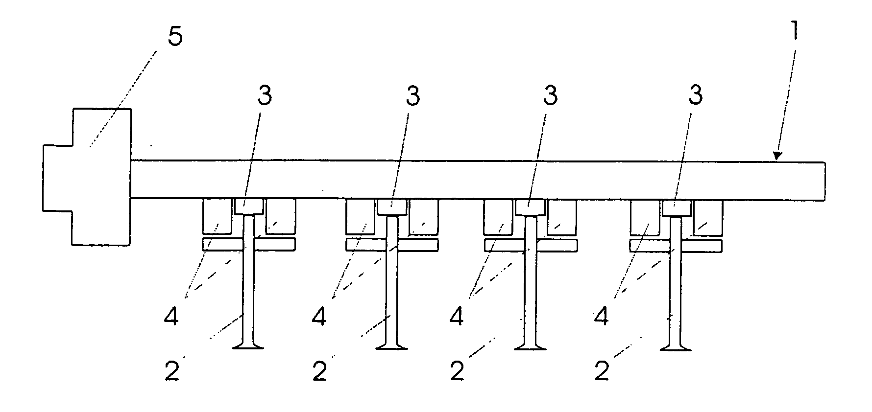
[0017]FIG. 1 shows in a very diagrammatic illustration a camshaft 1 of an internal combustion engine (not illustrated in its entirety). The camshaft 1 serves for activating a number of inlet valves 2 which in a way known per se control the inflow of air or of a fuel / air mixture to cylinders (likewise not illustrated) of the internal combustion engine. In the present case, the engine is a V8 engine with two camshafts 1 for altogether eight or sixteen inlet valves 2. The internal combustion engine also comprises outlet valves and a camshaft for controlling the same, but these are, for reasons of clarity, not illustrated.

[0018] In order to provide different lift levels for the inlet valves 2, the camshaft 1 comprises a number of partial lift cams 3 and a number of full lift cams 4, between which changeover can take place in order to bring them alternatively into engagement with the inlet valves 2. When the partial lift cams 3 are in engagement with the inlet valves 2, the valve lift i...


PUM


Abstract

In a method for changing the lift of inlet valves of an internal combustion engine between a partial lift and a full lift, the lift of the inlet valves being controlled by at least one camshaft, which comprises partial lift cams and full lift cams acting alternatively on the inlet valves, the control times of an inlet valves assigned to the camshaft are adjusted by rotating the camshaft by a certain angle so that the changeover between the partial lift cams and the full lift cams can be carried out at points within a characteristic performance graph of the internal combustion engine at which the suction capacity of the internal combustion engine when using the partial lift cams corresponds essentially to the suction capacity of the internal combustion engine when using the full lift cams.

Description

[0001] This is a Continuation-In-Part Application of International Application PCT / EP2004 / 003338 filed Mar. 30, 2004 and claiming the priority of German application 103 21 881.5 filed May 15, 2003.BACKGROUND OF THE INVENTION [0002] The invention relates to a method for changing the lift of inlet valves of an internal combustion engine between a partial lift and a full lift under the control of at least one camshaft having partial lift cams and full lift cams. [0003] Such a method is known from MTZ 61 (2002), pages 730-746. In this method, changeover is effected between an inner tappet and an outer tappet, which are assigned to different cam profiles and act on the inlet valve, by means of a controllable cup tappet. The inner tappet or partial lift cam is designed in such a way that it generates a lift of the inlet valve of roughly 3 mm, whereas the outer tappet or full lift cam generates an inlet valve lift of roughly 12 mm. [0004] For low power requirements of the internal combusti...

Claims


Application Information

Patent Timeline
Patent Type & Authority Applications(United States)
IPC IPC(8): F01L1/34F01L1/46F01L13/00F02D13/02
CPCF01L1/46F01L13/0015Y02T10/18F01L2800/00F02D13/0226F01L13/0031Y02T10/12
Inventor GLOSE, MARTINKUDASHEV, ARKADI
Owner DAIMLER AG
Why Eureka
Try Eureka