Rock drill bit having outer and inner rock-crushing buttons

Inactive Publication Date: 2006-03-23
SANDVIK INTELLECTUAL PROPERTY AB
View PDF17 Cites 29 Cited by
  • Summary
  • Abstract
  • Description
  • Claims
  • Application Information

AI Technical Summary

Benefits of technology

[0005] The present invention has an object of providing a rock drill b

Problems solved by technology

In some cases the cavity has been clogged by debris.
T

Method used


Image

  • Rock drill bit having outer and inner rock-crushing buttons
  • Rock drill bit having outer and inner rock-crushing buttons
  • Rock drill bit having outer and inner rock-crushing buttons

Examples


Embodiment Construction

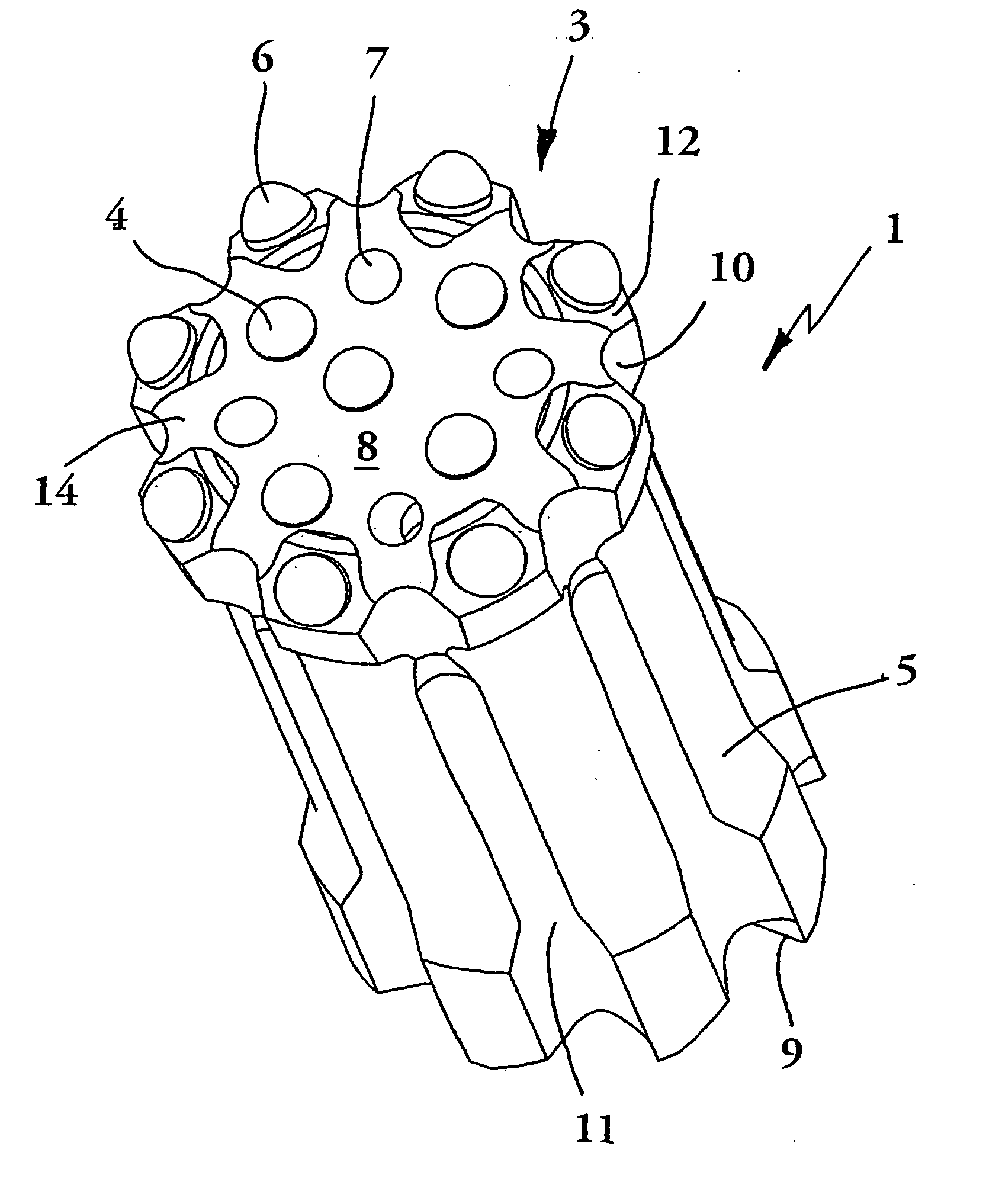
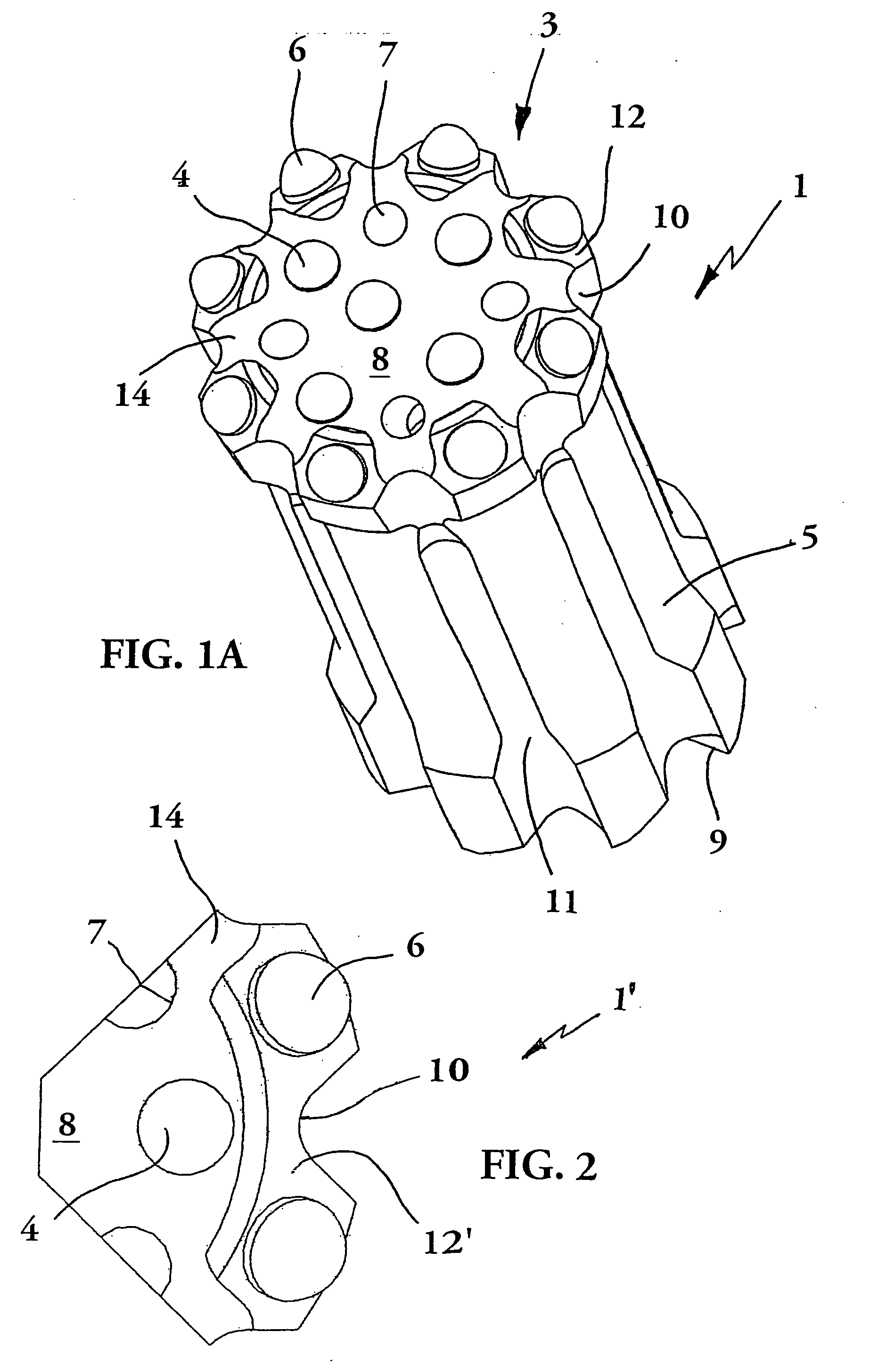
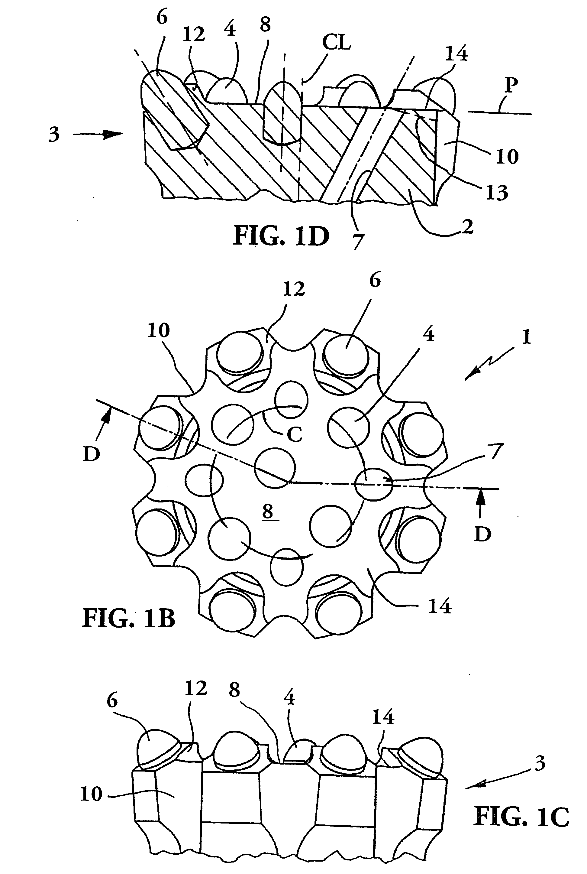
[0017] The percussive rock drill bit 1 illustrated in FIGS. 1A-1D comprises a bit body 2 having a head portion or a drill head 3 and a shank or a skirt 5. The drill head 3 and the skirt 5 are rigidly integrated with each other. A drill rod, not shown, is supposed to be connected to the rock drill bit 1 via a thread coupling. In the drill rod, a through-going flush duct is arranged in a conventional way. A longitudinal center axis CL of the rock drill bit 1 is shown in FIG. 1D. The rock drill bit 1 is preferably provided with an internal (female) thread, not shown, supposed to receive an external (male) thread at one end of the drill rod.

[0018] The drill head 3 of the rock drill bit 1 according to the present invention is provided with rock removing members preferably in the form of cemented carbide buttons, i.e., front or inner buttons 4 and peripheral buttons 6. At least one cooling medium channel 7 extends between an internal space of the rock drill bit 1 (which is surrounded by ...


PUM


Abstract

A rock drill bit for percussive drilling includes a front face which has radially outer and inner portions. Fluid channels are disposed in the head portion in communication with the inner portion of the front face. The inner portion of the front face carries a plurality of front buttons. The outer portion comprises circumferentially spaced steel portions which are axially raised relative to the inner portion. Each raised portion carries one or two peripheral buttons located radially outwardly of an imaginary circle which intersects at least two of the front buttons and at least two of the flushing channels. The imaginary circle is arranged coaxially relative to the center axis.

Description

[0001] The present application claims priority under 35 U.S.C. § 119 to Patent Application Serial No. 0402283-6 filed in Sweden on Sep. 21, 2004. TECHNICAL FIELD OF THE INVENTION [0002] The present invention relates to a rock drill bit for percussive drilling, especially top hammer drilling. [0003] From U.S. Pat. No. 5,890,551 a rock drill bit is previously known, which has an appurtenant drill rod. The rock drill bit at the front face thereof is provided with cemented carbide buttons that work the rock by impacting thereupon during simultaneous rotation. A cavity is formed in the front face, and a fluid channel extends through the drill bit for supplying flushing fluid to the cavity. The cavity is completely bordered by an endless land. Some of the buttons are mounted in the land. Others of the buttons are mounted in the cavity in order to be cooled and flushed by a cushion of flushing fluid created in the cavity. In some cases the cavity has been clogged by debris. [0004] U.S. Pat...

Claims


Application Information

Patent Timeline
IPC IPC(8): E21B10/36E21BE21B10/38E21B10/56
CPCE21B10/56E21B10/38E21B10/00
Inventor HADIN, PER-OLABJORK, FREDRIK
Owner SANDVIK INTELLECTUAL PROPERTY AB
Why Eureka
Try Eureka