Method for manufacturing a vehicle interior paneling part, and vehicle interior paneling part

a technology for interior paneling and vehicle body, which is applied in the direction of vehicle body, monocoque construction, domestic articles, etc., can solve the problem of needing multiple method steps, and achieve the effect of fast and cheaper

Inactive Publication Date: 2006-03-23
TRW AUTOMOTIVE SAFETY SYST
View PDF4 Cites 5 Cited by
  • Summary
  • Abstract
  • Description
  • Claims
  • Application Information

AI Technical Summary

Benefits of technology

[0004] Therefore, according to the present invention, provision is made that the decorative part is already joined to the cover plate during the injection- or foam-molding process. In this context, provision is made that the decorative part has a front part that is visible in the assembled state and an anchor part that extends therefrom on a reverse side, the decorative part being positioned in one of an injection and foaming mold. Subsequently, one of an injection- and foam-molding process is carried out around the decorative part to generate the cover plate and to embed the anchor part at least partially in the cover plate. Therefore, the cover plate is joined to the decorative part as the cover plate is manufactured, which renders the method faster and cheaper.
[0005] In this context, the anchor part can be designed in different ways. For example, the anchor part can have an undercut, into which liquid plastic flows during the injection- or foam-molding process. As a result, the anchor part becomes altogether narrower, which also makes the decorative part lighter. In addition, a form-locking connection between the decorative part and the cover plate is assured, so that the decorative part cannot be pressed in when pressure is exerted on the decorative part from outside, for example by a vehicle occupant.
[0009] According to the preferred embodiment, provision is made that the decorative part is embedded in the cover plate in a form-locking manner, the decorative part having portions extending transverse with respect to a visible surface of the cover plate and portions extending perpendicular thereto, the portions being embedded in the cover plate. This prevents the decorative part from shifting or detaching.
[0011] An especially high-quality impression is achieved when the decorative part is made of metal.

Problems solved by technology

The disadvantage of this method is that a plurality of method steps is necessary in order to attach a decorative part of this type to a cover plate.

Method used


Image

  • Method for manufacturing a vehicle interior paneling part, and vehicle interior paneling part
  • Method for manufacturing a vehicle interior paneling part, and vehicle interior paneling part
  • Method for manufacturing a vehicle interior paneling part, and vehicle interior paneling part

Examples


Embodiment Construction

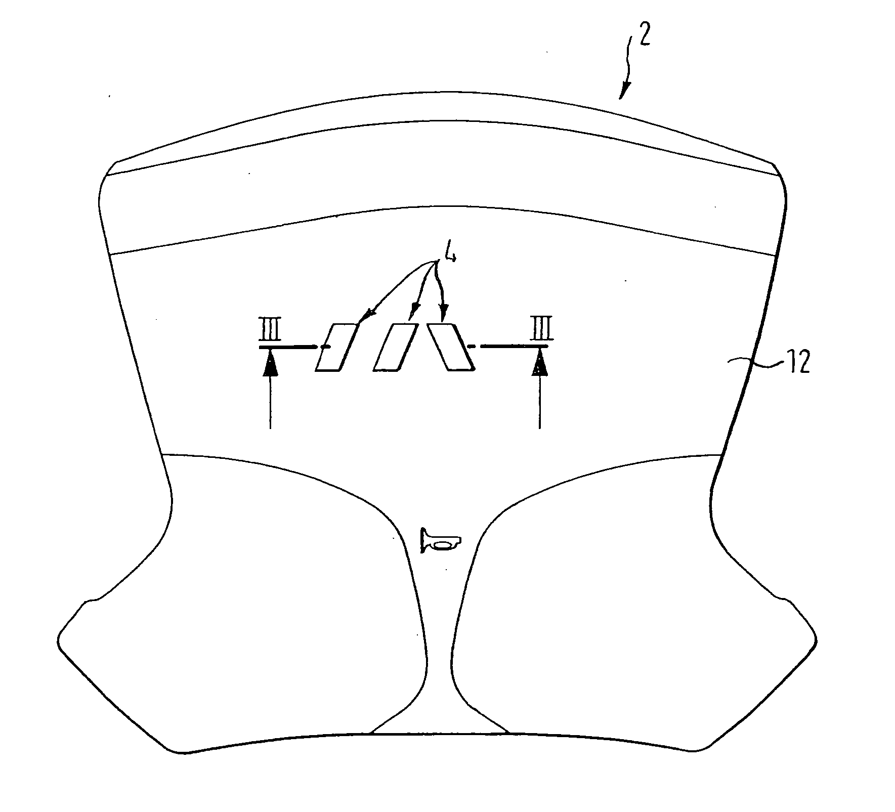
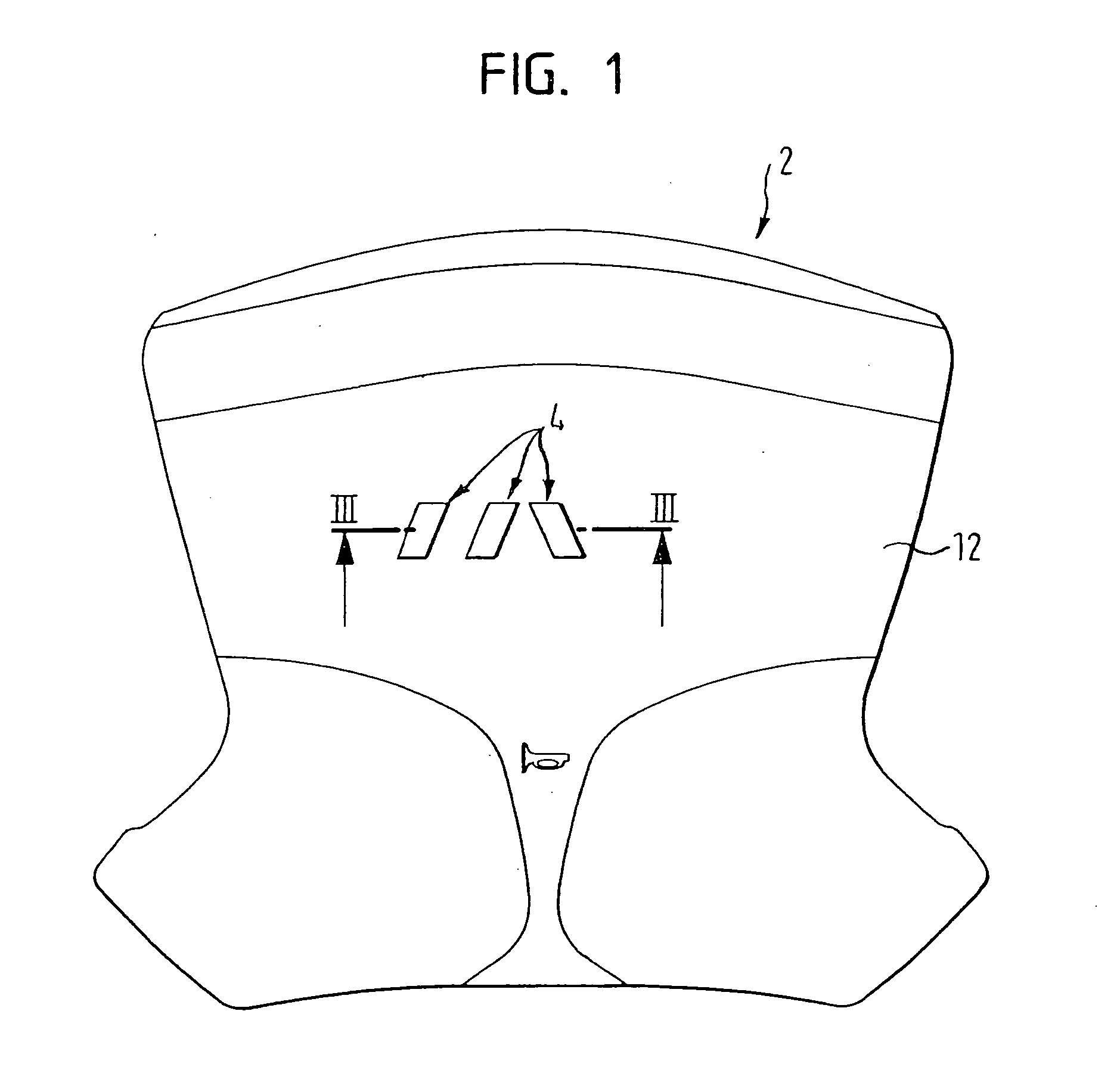
[0018]FIG. 1 depicts a vehicle interior paneling part in the form of a gas bag cover 2, made up of a cover plate 12 and decorative parts 4 that are visible on the front side.

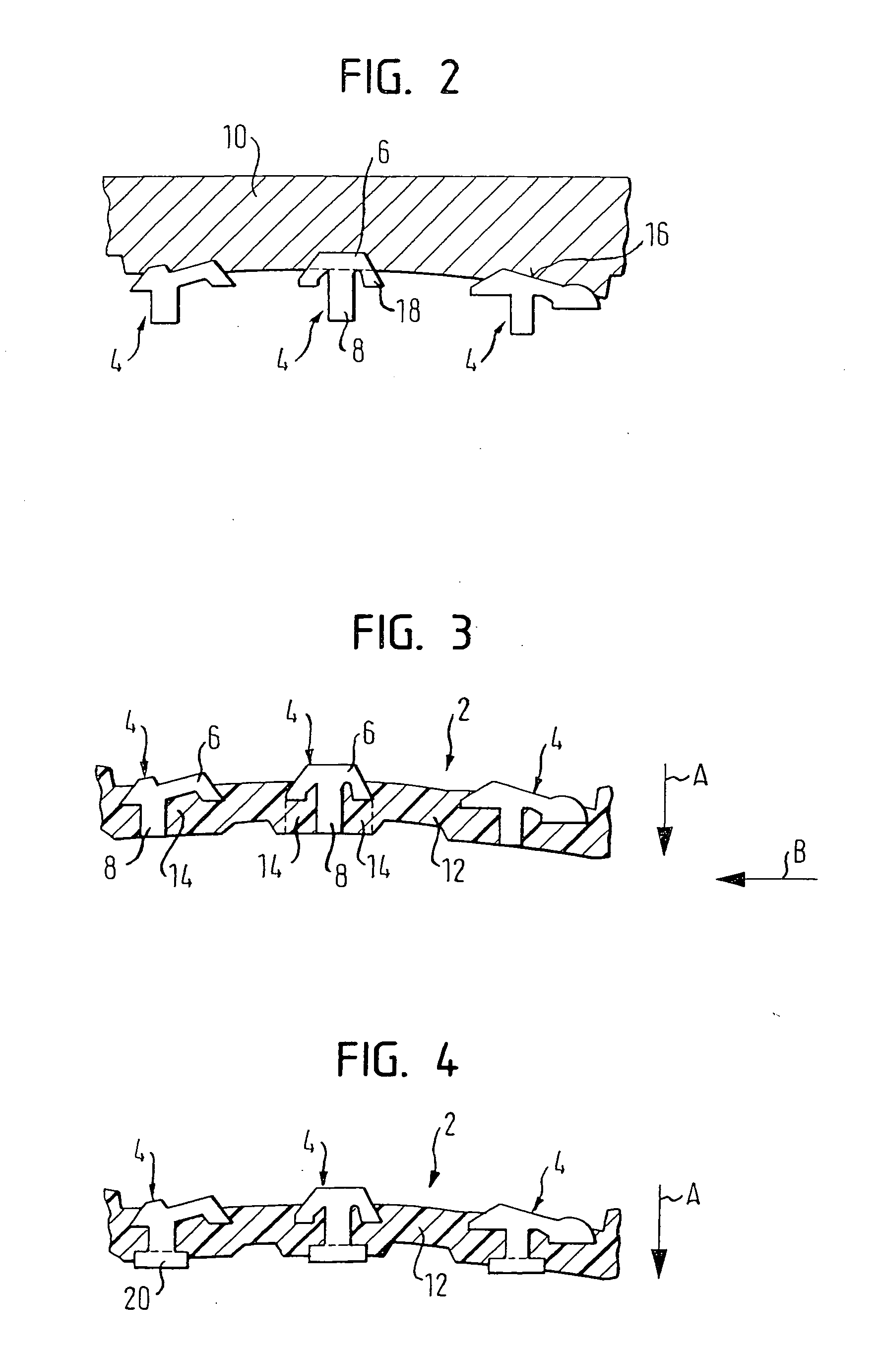
[0019]FIG. 2 depicts an upper part of an injection or foaming mold 10, for manufacturing the gas bag cover 2 shown in FIG. 1. Foaming mold 10 has recesses 16, into which, for positioning purposes, decorative parts 4 partially extend before the injection- or foam-molding process. In this context, each decorative part 4 can be subdivided into two imaginary sections, a front part 6 and an anchor part 8. Front part 6 is completely accommodated in recess 16 of foaming mold 10, the recess being complementary to the front side, and anchor part 8 is situated outside of recess 16. Anchor part 8 has a section 18 that immediately adjoins front part 6, section 18 extending preferably obliquely outwards and towards the reverse side of cover plate 12, i.e., the “head” of decorative part 4 obliquely converges in the direction...


PUM

PropertyMeasurementUnit
dimensionaaaaaaaaaa
pressureaaaaaaaaaa
weightaaaaaaaaaa

Abstract

A method for manufacturing a vehicle interior paneling part, especially a gas bag cover, includes the positioning of a decorative part in one of an injection and foaming mold, the decorative part having a visible front part in the assembled state and an anchor part that extends therefrom on a rear side. A subsequent partial injection- or partial foam-molding around the decorative part takes place to generate a cover plate and to embed the anchor part at least partially in the cover plate. Thereby, a vehicle interior paneling part is produced.

Description

TECHNICAL FIELD [0001] The present invention relates to a method for manufacturing a vehicle interior paneling part, as well as a vehicle interior paneling part. BACKGROUND OF THE INVENTION [0002] U.S. Pat. No. 5,685,056 discloses a method, in which, in a first step, a large-surface cover plate of a gas bag cover made of plastic is injection molded. In a second step, an emblem is inserted into a hole in the cover plate. The emblem has an extension, which extends through the hole and protrudes from the opposite side of the cover plate. The protruding section is then crimped, as a result of which it is supported on the opposite side of the cover plate. Subsequently, the decorative part is securely attached to the cover plate. [0003] The disadvantage of this method is that a plurality of method steps is necessary in order to attach a decorative part of this type to a cover plate. This in turn results in increased costs, which are to be avoided. BRIEF SUMMARY OF THE INVENTION [0004] The...

Claims


Application Information

Patent Timeline
Patent Type & Authority Applications(United States)
IPC IPC(8): B60J7/00B60R21/215
CPCB29C44/1214B29C45/14065B29C45/14336B60R2021/21543B29L2031/3038B60R13/02B60R21/215B29C45/14418
Inventor SCHUETZ, DOMINIKHEIMBERGER, MANFREDMISSBACH, KONRAD
Owner TRW AUTOMOTIVE SAFETY SYST
Why Eureka
Try Eureka