Calibration circuit for a driver control circuit, and driver control circuit

Active Publication Date: 2006-03-23
INFINEON TECH AG
View PDF8 Cites 0 Cited by
  • Summary
  • Abstract
  • Description
  • Claims
  • Application Information

AI Technical Summary

Benefits of technology

[0022] It is an object of the present invention to control the input/output drivers of a microchip cost-effectively in such

Problems solved by technology

Since the output resistance of the input/output drivers is subject to severe fluctuations both on account of the production tolerances and on account of the respective operating conditions, regulating the output resistance of the input/output driver to the resistance of the output line is a difficult technical problem of regulation.
External resistors are

Method used


Image

  • Calibration circuit for a driver control circuit, and driver control circuit
  • Calibration circuit for a driver control circuit, and driver control circuit
  • Calibration circuit for a driver control circuit, and driver control circuit

Examples


Example

[0060] Identical or functionally identical elements and signals—unless specified otherwise—have been provided with the same reference symbols in all the figures.

[0061] Although the present invention is described below with regard to calibration circuits and driver control circuits, it is not restricted thereto, but rather can be used in diverse ways.

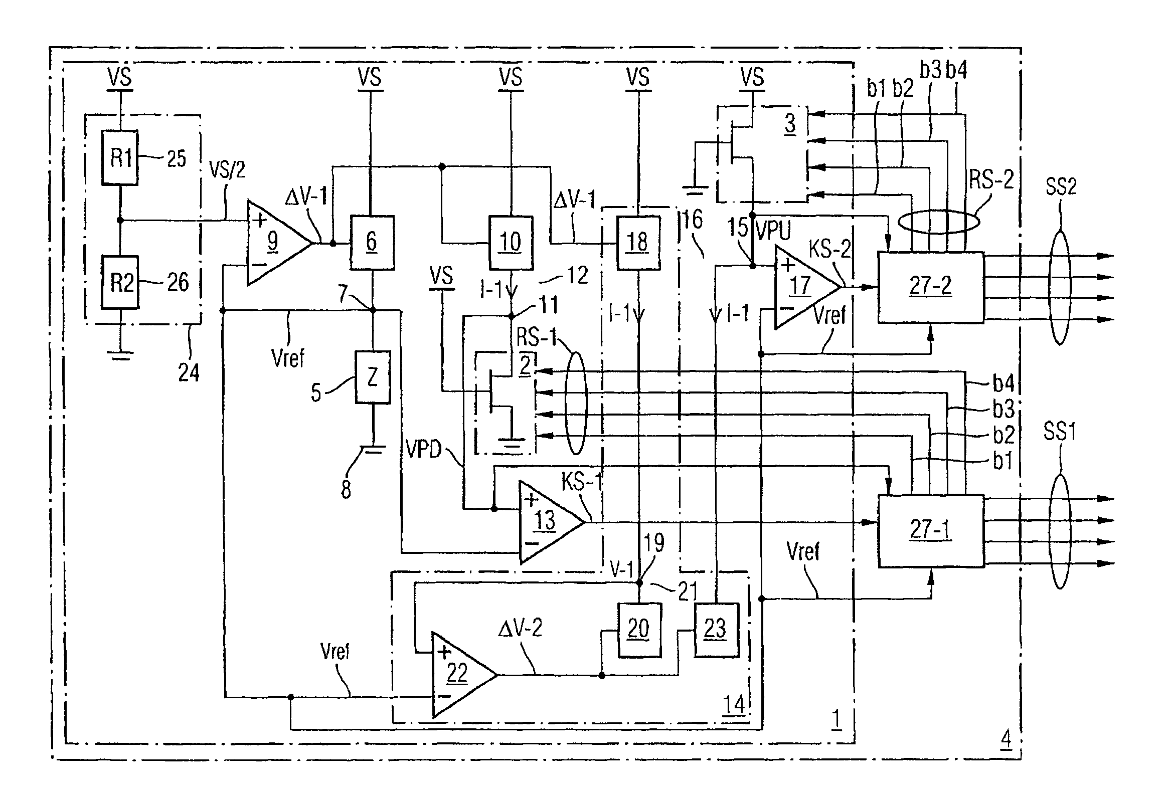
[0062]FIG. 4 shows a schematic block diagram of a preferred exemplary embodiment of a driver control circuit with a calibration circuit according to the present invention. The driver control circuit 4 has a calibration circuit 1, a first control signal generating circuit 27-1 and a second control signal generating circuit 27-2.

[0063] The calibration circuit 1 regulates a first calibration signal KS-1 for a pull-down driver 2 and a second calibration signal KS-2 for a pull-up driver 3 in such a way that the calibration error of the corresponding calibration signal is reduced in each case. The regulating error of the driver control circ...


PUM


Abstract

A calibration circuit of a driver control circuit which controls a plurality of input/output drivers of an integrated circuit comprises first and second voltage/current converters, first, second and third comparators and a voltage/current converter circuit. The first voltage/current converter with an external resistor provides a reference voltage to half the value of a supply voltage of the calibration circuit. The second voltage/current converter is connected to a first pull-down driver whose pull-down driver voltage is set to half the supply voltage. The second comparator compares the reference voltage with the pull-down driver voltage to provide a first calibration signal. The voltage/current converter circuit is connected to a pull-up driver whose pull-up voltage is set to half the value of the supply voltage. The third comparator compares the reference voltage with the pull-up driver voltage in order to provide a second calibration signal.

Description

BACKGROUND OF THE INVENTION [0001] 1. Field of the Invention [0002] The invention relates to a calibration circuit for reducing a respective calibration error of a first calibration signal for a pull-down driver and a second calibration signal for a pull-up driver of a driver control circuit for controlling N input / output drivers of an integrated circuit and to such a driver control circuit. [0003] 2. Description of the Prior Art [0004] The technical field of the invention relates to the transmission of signals from a microchip to other components or microchips by means of output lines or microchip output lines. An individual microchip has a multiplicity of output lines. The signals that are transmitted via the output line of the microchip are driven by means of an input / output driver (I / O driver). In order to minimize or to avoid the reflection of transmitted signal energy on an output line, thus reducing or avoiding noise on the output line, the output resistance of the input / outp...

Claims


Application Information

Patent Timeline
IPC IPC(8): H03K19/0175
CPCH04L25/0278H03K19/0005
Inventor COSTA, VINCENZOMULLER, CHRISTIAN
Owner INFINEON TECH AG
Why Eureka
Try Eureka