Data transmission method and system thereof, portable terminal, and data receiver

a data transmission and data technology, applied in the field of data transmission methods and their systems, portable terminals, and data receivers, can solve the problems of system inconvenient everyday use, overload of networks, and large communication costs, and achieve the effect of convenient use, volume of data, and convenient data transmission

Active Publication Date: 2006-03-23
KDDI CORP
View PDF10 Cites 45 Cited by
  • Summary
  • Abstract
  • Description
  • Claims
  • Application Information

AI Technical Summary

Benefits of technology

[0012] With the exemplary embodiments according to the invention, it is possible to easily transmit data at high-speed through optical open transmission. Since a signal light with a narrow beam angle can be used, high-speed data transmission is realized. A data is transmitted at

Problems solved by technology

As the number of pixels per picture increases, however, data volume of one image has extremely increased and, therefore, the above method to transmit image data for another units by attaching the data to e-mail causes overloads of networks and also the communication costs are mounted up to the large sum.
Although it is possible to easily obtai

Method used


Image

  • Data transmission method and system thereof, portable terminal, and data receiver
  • Data transmission method and system thereof, portable terminal, and data receiver
  • Data transmission method and system thereof, portable terminal, and data receiver

Examples


first embodiment

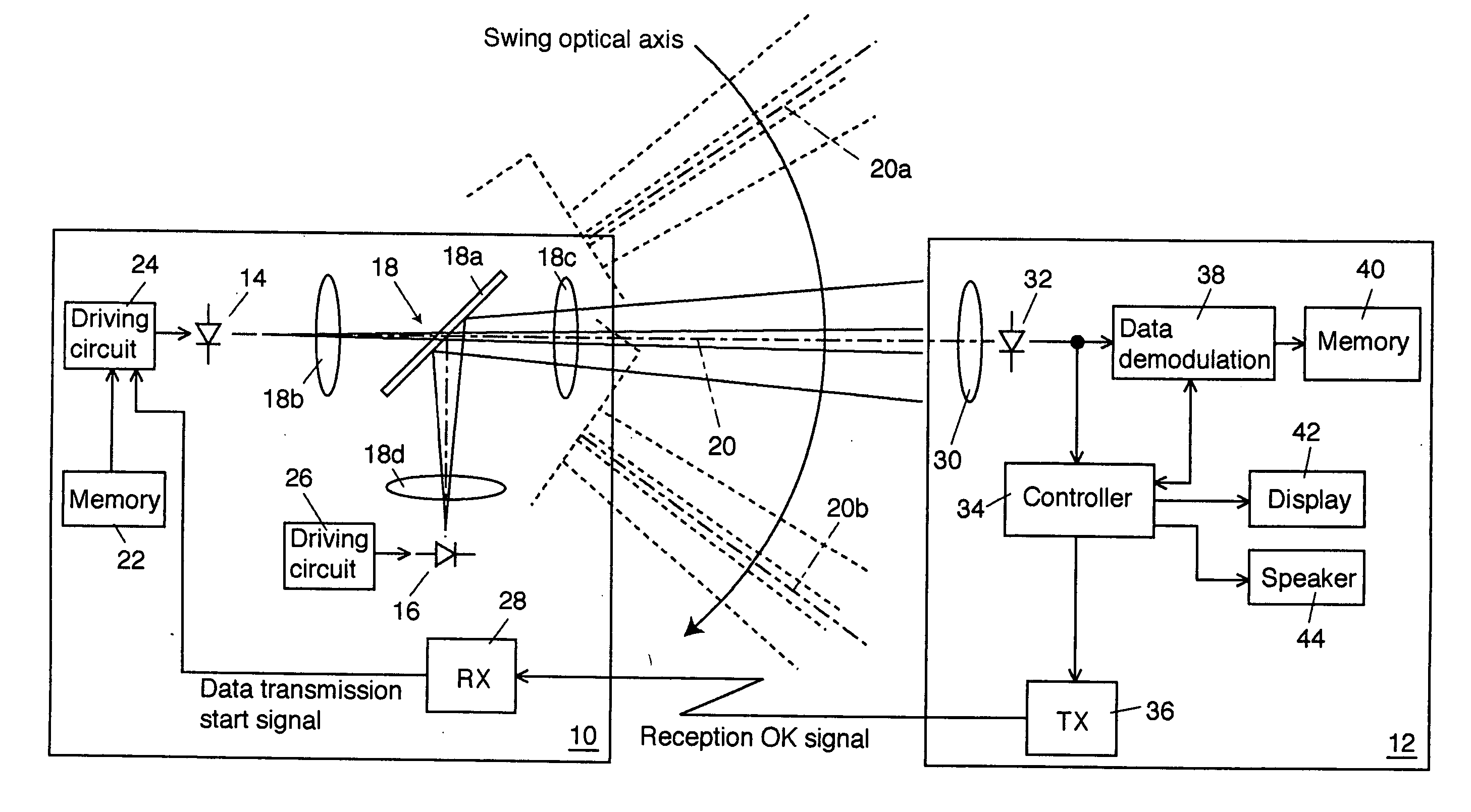
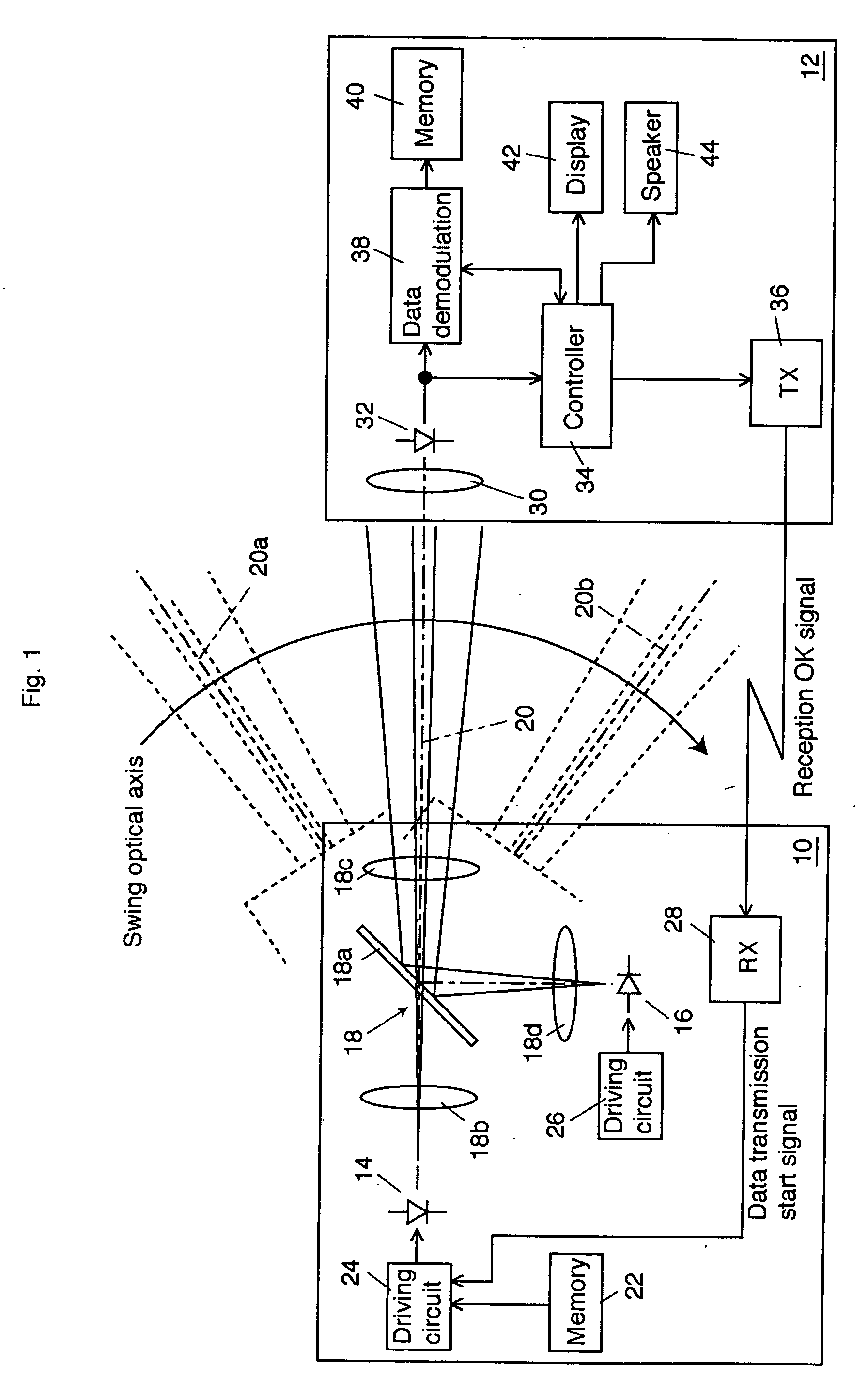
[0064] Because the beam spread of the signal light is set small, a sufficient light intensity of signal light can enter the photodiode 132. Consequently, the transmission rate of the signal light can be set to as fast as 1 Gbps. The signal light goes across the photodiode 132 momentarily but for a longer period compared to the first exemplary embodiment and accordingly the signal light can enter the photodiode 132 for a longer period compared to the Although the period in which the signal light enters the photodiode 132 is very short as stated above, since the data transmission rate is sufficiently fast, even an image data of 1 MB, for example, can be transmitted from the data transmitter 110 to the data receiver 112 using this exemplary embodiment.

[0065] When the demodulation of the necessary data is successfully completed, the display 142 indicates that the data was successfully received. When the data reception was not successfully completed because of the disconnection of open ...

second exemplary embodiment

[0068] It is also applicable that a plurality of photodiodes are disposed in parallel to photoreceive laser beams from a broader range. FIG. 5 shows a schematic block diagram of a third exemplary embodiment in which the data receiver 112 of the second exemplary embodiment is modified.

[0069] In a data receiver 112a, a photodiode array including a plurality of photodiodes 152-1 to 152-n is disposed on a condensing surface of a lens 150 to condense signal lights and an adder 154 adds electrical signals output from the photodiodes 152-1 to 152-n. The plurality of photodiodes 152-1 to 152-n can be disposed either linearly like a line sensor or two-dimensionally like a camera image sensor. The adder 154 is realized on a wired OR circuit. An electrical signal output from the adder 154 is applied to the controlling circuit 134 and the data demodulating circuit 138. The operations of the other components of the data demodulator 112a are the same with those of the second exemplary embodiment ...


PUM


Abstract

In a data transmission method according to an exemplary embodiment, a data transmitter, which is capable of outputting a dummy light for judging an optical axis and a signal light having a beam spread smaller than that of the dummy light on the same optical axis, outputs the dummy light for scan so as to go across a photoreceiving part of a data receiver. When the dummy light having a predetermined optical level or more is optically received, the data receiver informs the data transmitter of reception chance and prepares for receiving the data. The data transmitter outputs the data carried by the signal light to the data receiver according to the information indicating the reception chance from the data receiver. The data receiver receives the data by optically receiving the signal light from the data transmitter.

Description

CROSS REFERENCE TO RELATED APPLICATIONS [0001] This application claims priority to Japanese Patent Application No. 2004-248688, filed on Aug. 27, 2004, the entire contents of which are incorporated herein by reference. FIELD OF THE INVENTION [0002] This invention relates to a data transmission method and its system, a portable terminal, and a data receiver. BACKGROUND OF THE INVENTION [0003] Owing to the conditions that a lot of sorts of portable terminals have functions of image processing, especially the functions of digital camera, there is a great need for massive data transmission. A portable terminal with a built-in digital camera is capable of recording still images and moving images and accordingly methods for transmitting such image data to the outside have been in demand. A method generally used at present is to attach image data to e-mails. [0004] As the number of pixels per picture increases, however, data volume of one image has extremely increased and, therefore, the a...

Claims


Application Information

Patent Timeline
IPC IPC(8): G11B7/00H04B10/077H04B10/079H04B10/11H04B10/112H04B10/524H04B10/54H04B10/564
CPCH04B10/116H04B10/1143
Inventor YAZAKI, TOMONORIUSAMI, MASASHI
Owner KDDI CORP
Why Eureka
Try Eureka