

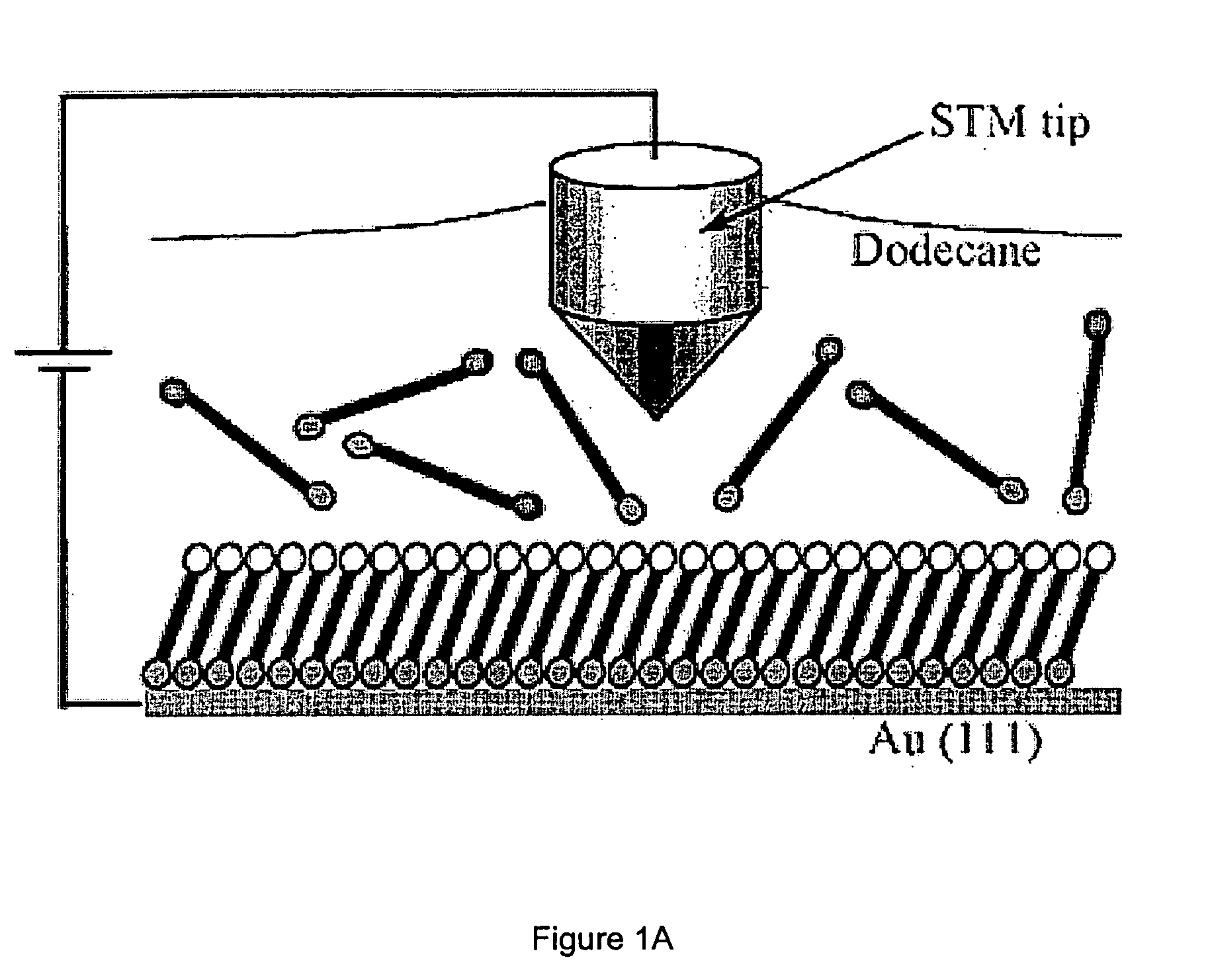
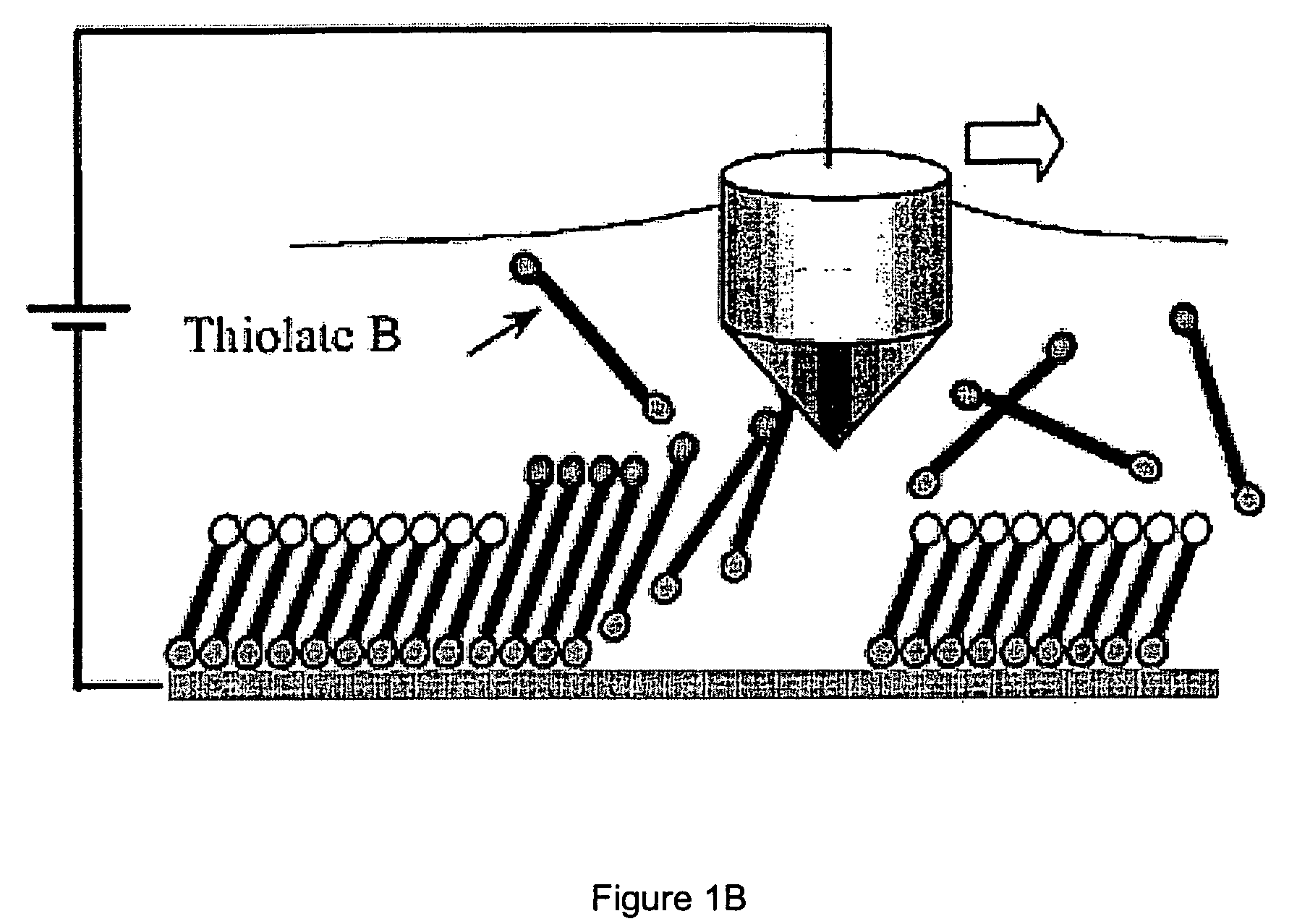
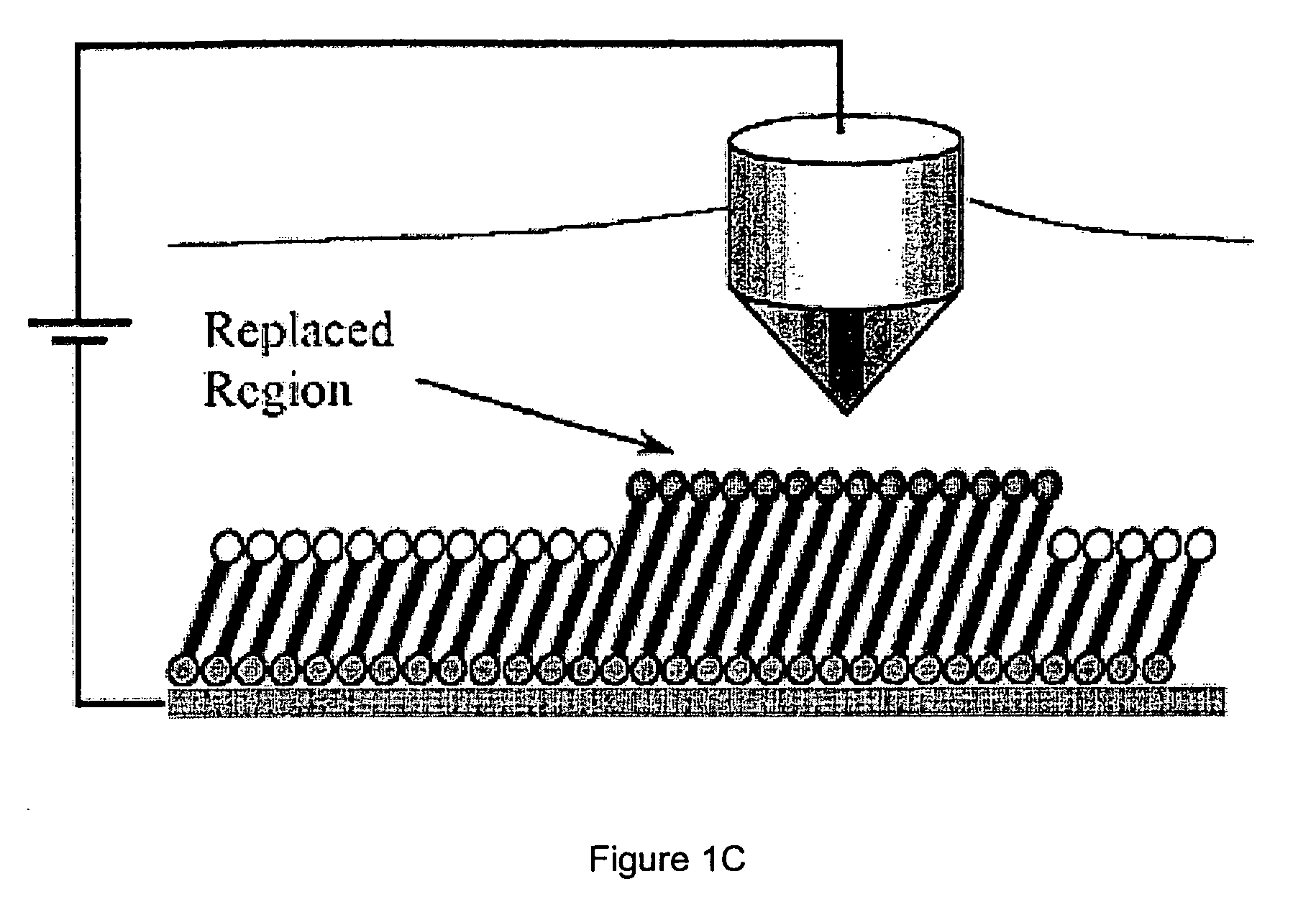
Gradient fabrication to direct transport on a surface
a technology of direct transport and chemical gradients, applied in the field of surfacebound chemical gradient production, can solve the problems of not finding application in the field of molecular machines, and none of the described studies, which employ stm-based replacement lithography to fabricate surfacebound static or dynamic gradients, etc., and achieves low driving force and high driving force
- Summary
- Abstract
- Description
- Claims
- Application Information
AI Technical Summary
Benefits of technology
Problems solved by technology
Method used
Image

Examples
example 1
Laboratory Example 1
[0269] One embodiment of a line raster pattern that can be employed in the fabrication of a gradient is disclosed. A line spacing of 12 nm is employed to form an area of diffuse coverage and is incrementally decreased in steps of about 2.5 nm to 5 nm to form an area of high coverage (i.e., the areas where desorption of matrix material and substitution of patterning material for matrix material is more complete). Since the average line resolution of this technique is 10 to 15 nm, this generates a gradient in which there is very little overlap of substitution lines in the diffuse coverage area and complete overlap of substitution lines in the high coverage area. This level of detail and resolution can be achieved, in part, due to the plurality of parameters that can be optimized. See FIG. 10.
example 2
Laboratory Example 2
[0270] Nanostructures were obtained by systematic variation in the replacement bias to promote thiolate desorption. The lithographic pattern 25 contains two rows of six parallel lines, each 200 nm in length, and separated by 100 nm. In this example, the lithographic scan rate (50 nm / s), tunneling set point current (8 pA), and relative humidity (57%) were kept constant, while the replacement bias was incrementally increased as each line was drawn. At low replacement bias (2.6-2.8 V), no substitution of FcC11SAc for C12S-SAM, the matrix material, occurred. As the replacement bias was increased, the extent of substitution increased. A bias range of 3.2-3.4 V gave optimal replacement of the FcC11SAc into the background SAM. As the replacement bias was further increased, the efficiency of substitution became less controllable. At higher bias, inconsistent line widths and etching of the Au substrate beneath the monolayer occurred. The latter can be observed by the dark...
example 3
Laboratory Example 3
[0273] A multidirectional gradient structure was fabricated. This gradient structure was fabricated to have high substitution coverage at the ends of the “L” shape, and diffuse coverage in the elbow region. The gradient structure was formed with a constant tunneling setpoint current (10 pA) and relative humidity (58%), but with systematic variation of the replacement bias, the scan rate, the length of lines being substituted, and the raster line spacing within the pattern. As the vertical leg of the “L” was formed, the replacement bias was varied from 2.95 V to 2.7 V, the scan rate was varied from 50 nm / s to 60 nm / s, the line length was varied from 150 nm to 70 nm and the raster line spacing was varied from 4 nm to 11 nm. The scan angle was then rotated 90 degrees and this process was repeated in reverse to draw the horizontal leg of the “L”. This example illustrates the ability to form complex gradient structures by employing the systematic variations described ...
PUM
| Property | Measurement | Unit |
|---|---|---|
| height | aaaaa | aaaaa |
| size | aaaaa | aaaaa |
| diameter | aaaaa | aaaaa |
Abstract
Description
Claims
Application Information