

Method for polishing substrate
a substrate and polishing technology, applied in the direction of grinding machine components, manufacturing tools, lapping machines, etc., can solve the problems of low polishing rate, low temperature of the surface of the polishing pad at the start of the next process, and inability to polish a single metal film, etc., to achieve the effect of easy detection
- Summary
- Abstract
- Description
- Claims
- Application Information
AI Technical Summary
Benefits of technology
Problems solved by technology
Method used
Image

Examples
embodiment 1
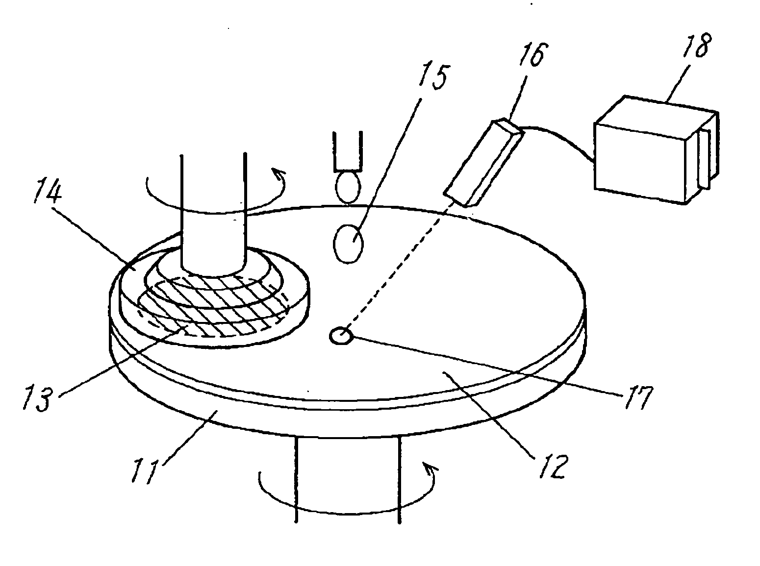
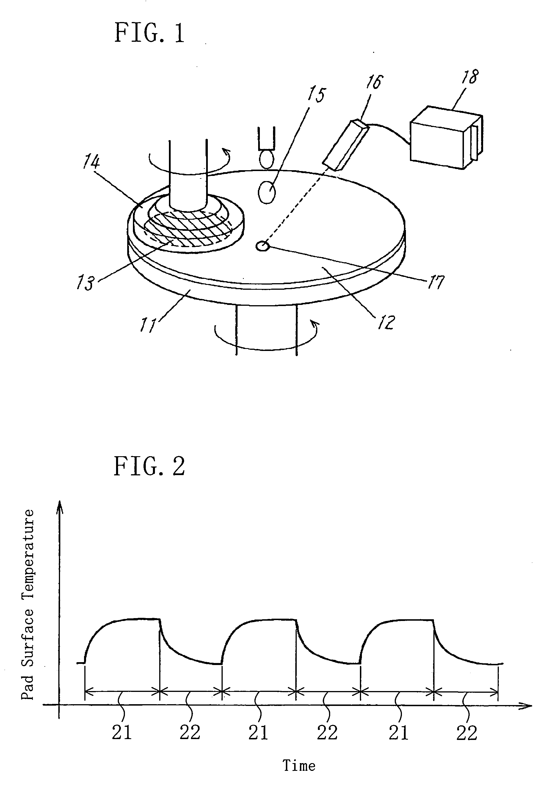
[0034] A first embodiment of the present invention will be described with reference to the drawings. FIG. 1 illustrates a polishing apparatus according to the first embodiment. As shown in FIG. 1, the polishing apparatus of this embodiment includes a platen 11 to which a polishing pad 12 is bonded and a carrier 14 for supporting a substrate 13. The substrate 13 is polished by rotating the platen 11 and the carrier 14 while supplying abrasives 15 to the polishing pad 12 with the substrate 13 pressed against the polishing pad 12.
[0035] The polishing apparatus further includes a sensor 16 for measuring the temperature of a surface of the polishing pad 12 and a monitoring tool 18 connected to the sensor 16. Therefore, the temperature of the polishing pad 12 surface can always be monitored. A part 17 of the polishing pad 12 to be measured in its surface temperature (hereinafter, referred to as “to-be-temperature-measured part 17”) is preferably set to overlap with a path through which t...
modification 1
of Embodiment 1
[0048] A first modification of the first embodiment of the present invention will be described hereinafter. In this modification, the rate of change of the temperature of a polishing pad 12 surface is used as an index of the amount of a substrate polished.
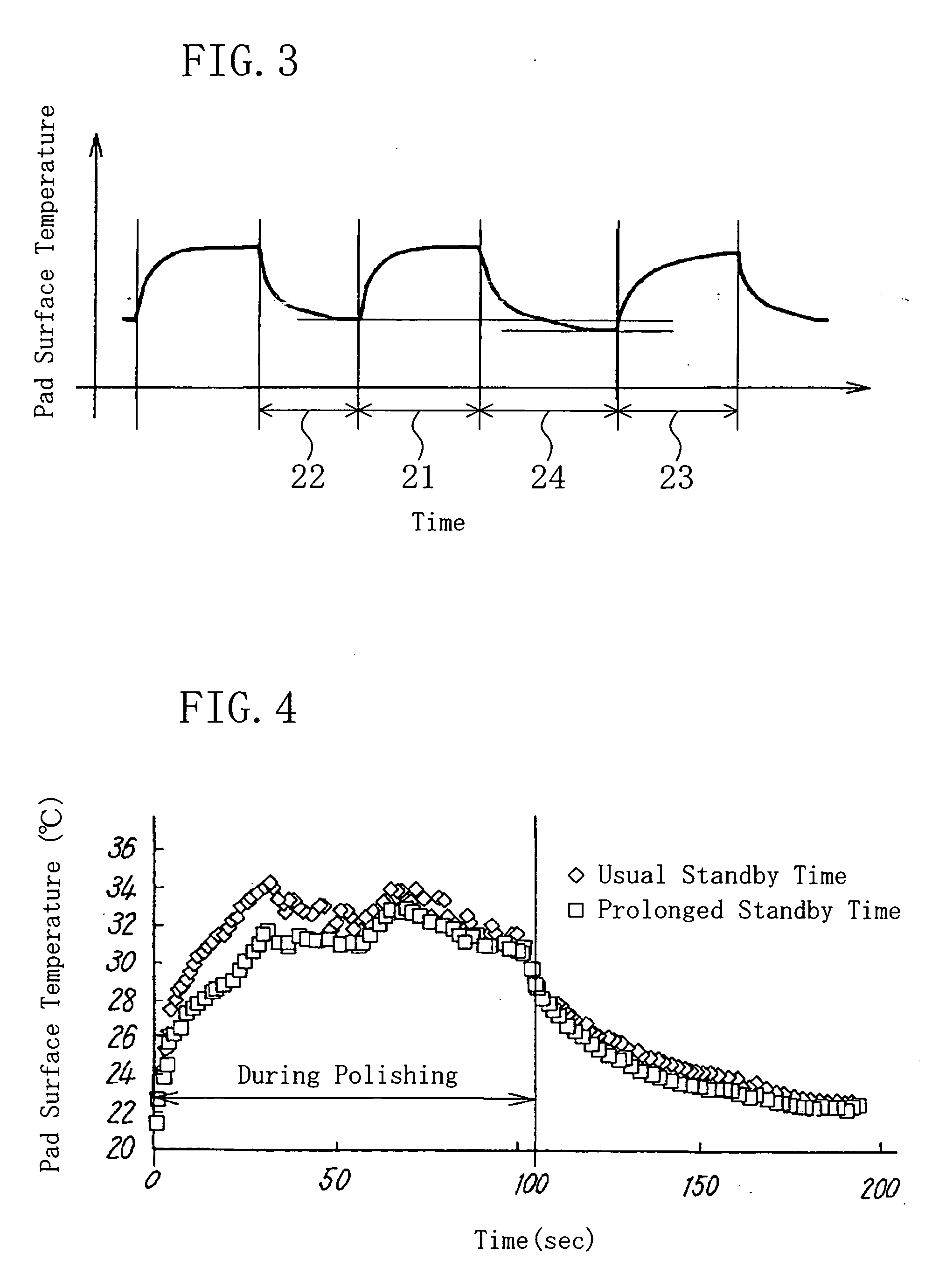
[0049]FIG. 7 is a graph showing the comparison on temperature variations at a polishing pad surface between a polishing step after the usual standby time and a polishing step after a prolonged standby time in a substrate polishing method of a first modification of the first embodiment of the present invention. In FIG. 7, the temperature variations at the polishing pad surface in the polishing step after the usual standby time and those at the polishing pad surface in the polishing step after the prolonged standby time are shown by a solid line and broken lines, respectively. The rate of change in the temperature of the polishing pad 12 surface in the polishing step after the usual standby time becomes smaller than t...
modification 2
of Embodiment 1
[0050] A second modification of the first embodiment of the present invention will be described hereinafter. With an increase in the intervals between polishing steps, the temperature of the polishing pad 12 surface is reduced. This increases the possibility of such an abnormality that part of a substrate is unpolished. FIG. 8 illustrates the relationship between the standby time between polishing steps and the polishing rate. As shown in FIG. 8, with an increase in the standby time, the polishing rate is reduced.
[0051] In view of the above, when the standby time between polishing steps is always monitored and a substrate processed after the standby time exceeding a previously set threshold value is eliminated, this can prevent a substrate that may have such an abnormality that part of the substrate is unpolished from being transferred to the next step.
[0052] A standby time beyond which an abnormality is caused is determined as a threshold value of the standby time ...
PUM
| Property | Measurement | Unit |
|---|---|---|
| Temperature | aaaaa | aaaaa |
Abstract
Description
Claims
Application Information