

Differential mechanism for a vehicle and method of forming the same
- Summary
- Abstract
- Description
- Claims
- Application Information
AI Technical Summary
Benefits of technology
Problems solved by technology
Method used
Image

Examples
Embodiment Construction
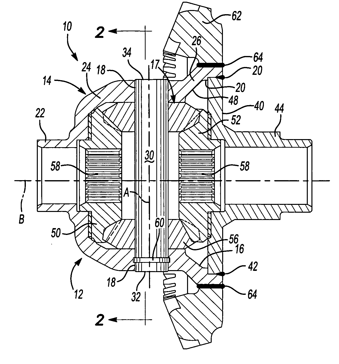
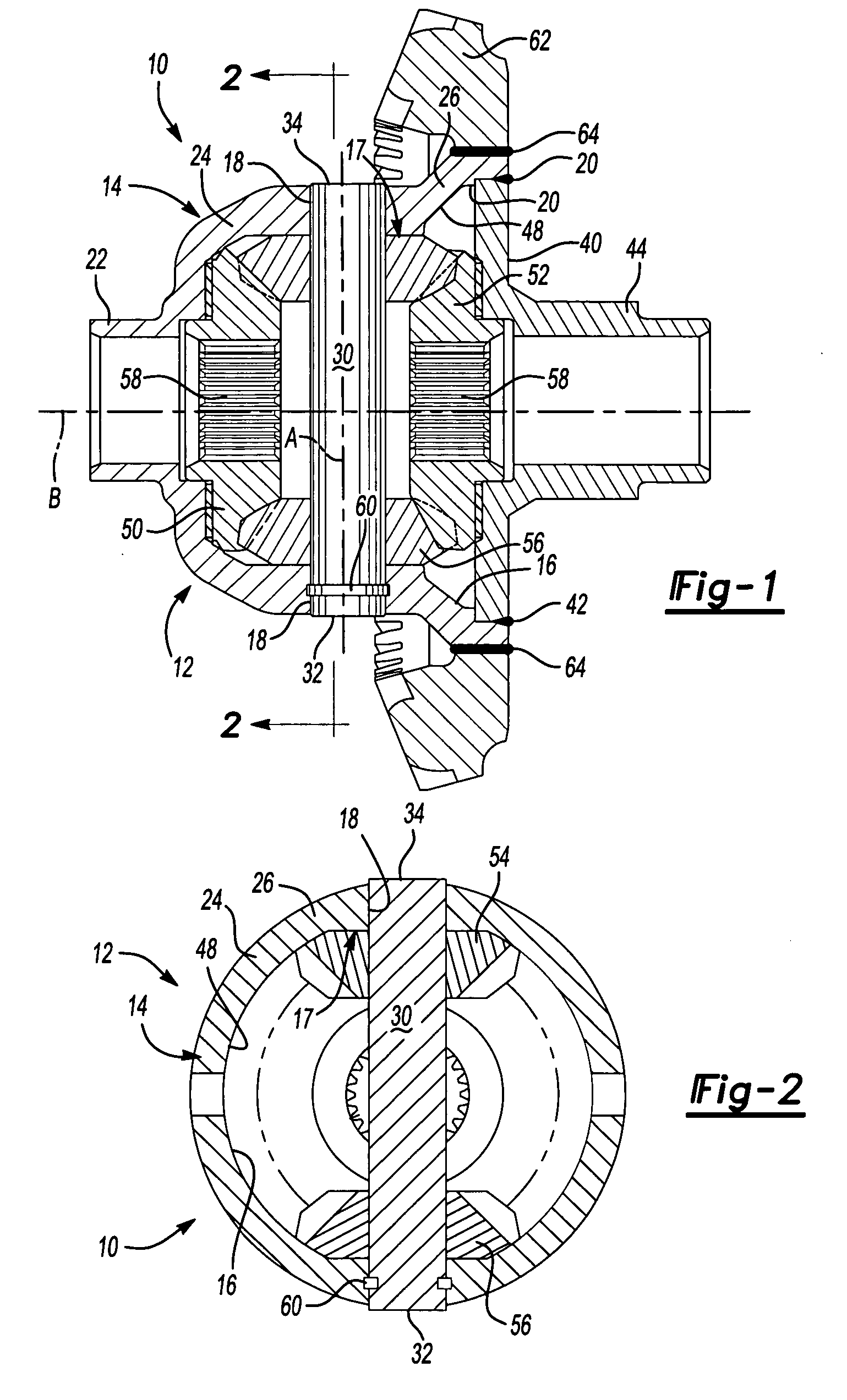
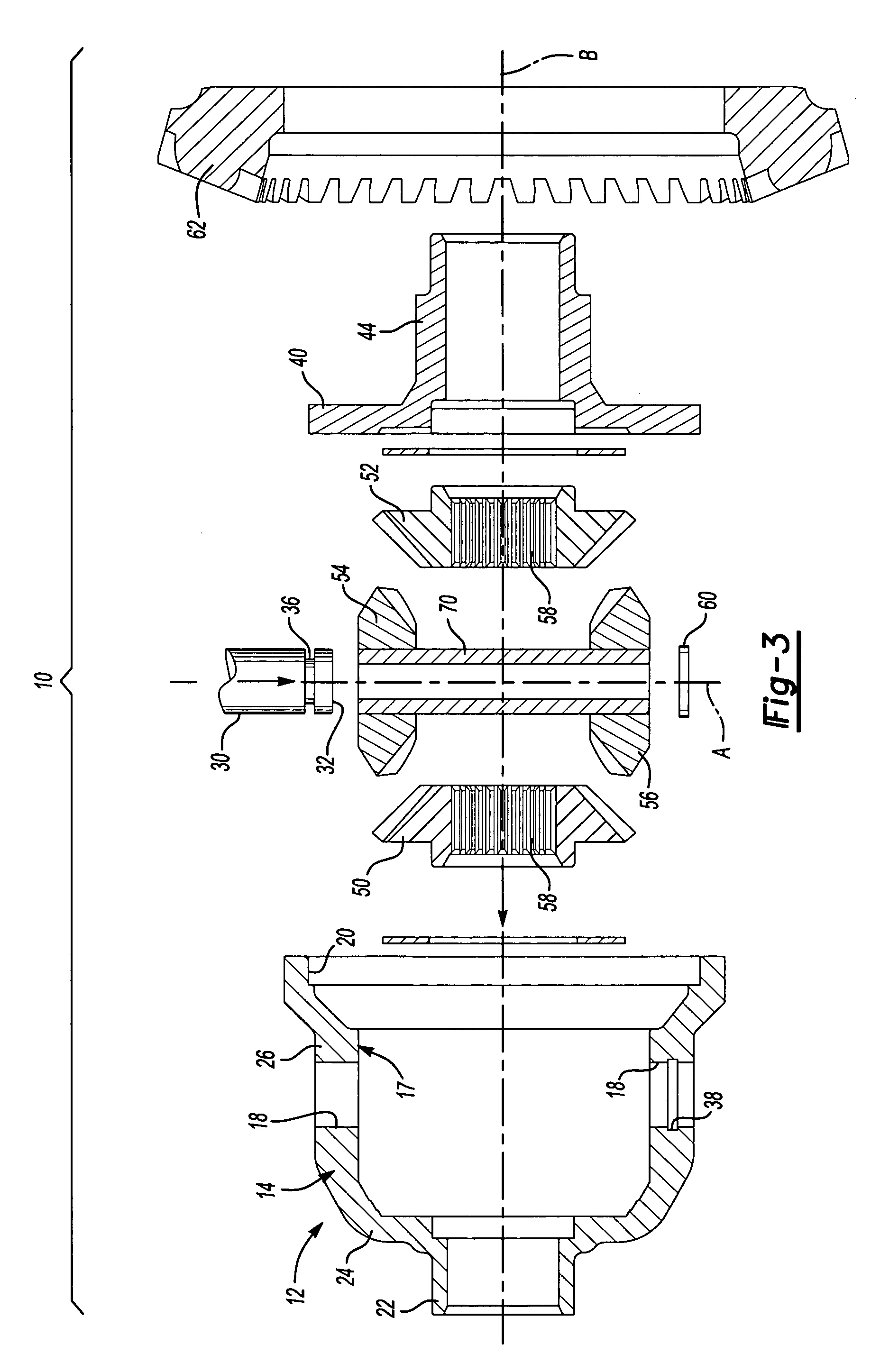
[0021] Referring to FIG. 1, a differential assembly of the present invention is generally shown at 10. A housing, generally shown at 12, includes a wall, generally indicated at 14. The wall 14 defines an inner surface 16. The inner surface 16 includes a generally planar section or surface, generally indicated at 17. At t least two receptors 18 diametrically disposed with respect to one another, are defined in the generally planar section 17. Alternatively, the inner surface 16 may include additional receptors (not shown). The wall 14 of the housing 12 defines an open end 20. The housing 12 defines a journal 22 at an opposite end of the housing 12 from the open end 20. The journal 22 may be formed apart from the housing 12 and then welded to the housing assembly, or may be formed integrally with the housing 12.
[0022] The housing 12 is formed by a spin-forming or flow-forming cold working operation that is particularly suited to produce bowl-shaped parts, and more particularly suited...
PUM
| Property | Measurement | Unit |
|---|---|---|
| Thickness | aaaaa | aaaaa |
Abstract
Description
Claims
Application Information