Electrostatic atomizing hairdryer and electrostatic atomizer

Inactive Publication Date: 2006-03-30
MATSUSHITA ELECTRIC WORKS LTD
View PDF9 Cites 50 Cited by
  • Summary
  • Abstract
  • Description
  • Claims
  • Application Information

AI Technical Summary

Benefits of technology

[0005] In the conventional electrostatic atomizing hairdryer described in Japanese Laid-Open Patent Publication No. 2002-151146, the electrostatic atomizer, however, is provided on outside of a main body of the hairdryer, so that the mist cannot be scattered effectively into airflow emitted from the main body of the hairdryer, and it is difficult to spray the mist to hair evenly in a short time. Therefore, a time necessary for treatment of hair becomes longer, and overdrying of hair may occur partially.
[0006] On the other hand, in an electrostatic atomizer for generating electrostatically atomized mist described in, for example, Japanese Laid-Open Patent Publication No. 2004-85185, high voltage is applied between an atomizing electrode and an opposing electrode so as to generate Rayleigh disrupture in water at front end of the atomizing electrode. The water repeats the disrupture with receiving large energy due to high voltage, so that mist of nanometer size with activated species of high reactivity is generated. Room air or incrustation on an indoor wall surface can be deodorized by such mist.
[0007] In order to scatter the mist effectively, an airflow path comprising a blower is provided in the electrostatic atomizer. The atomizing electrode and the opposing electrode are arranged in the airflow path, so that the mist is scattered with the airflow. In such a case, it is necessary to contain the atomizing electrode and the opposing electrode in a housing for electrostatic atomization to prevent that the liquid at the front end of the atomizing electrode is exposed to airflow in the airflow path directly and is evaporated. In addition, the electrostatically atomized mist generated at the front end of the atomizing electrode is moved toward the opposing electrode by electrostatic force, so that a mist emitting opening from which the mist is emitted to outside of the housing for electrostatic atomization is provided in the vicinity of the opposing electrode.
[0008] The mist, however, cannot be emitted efficiently from the mist emitting opening of the housing for electrostatic atomization even though the housing for elec

Problems solved by technology

In the conventional electrostatic atomizing hairdryer described in Japanese Laid-Open Patent Publication No. 2002-151146, the electrostatic atomizer, however, is provided on outside of a main body of the hairdryer, so that the mist cannot be scattered effectively into airflow emitted from the main body of the hairdryer, and it is difficult to spray the mist to hair evenly in a short time.
Therefore, a time necessary for treatment of hair becomes longer, and overdrying of hair may occur partially.
The mist, however, cannot be emitted efficiently from the

Method used


Image

  • Electrostatic atomizing hairdryer and electrostatic atomizer
  • Electrostatic atomizing hairdryer and electrostatic atomizer
  • Electrostatic atomizing hairdryer and electrostatic atomizer

Examples


first embodiment

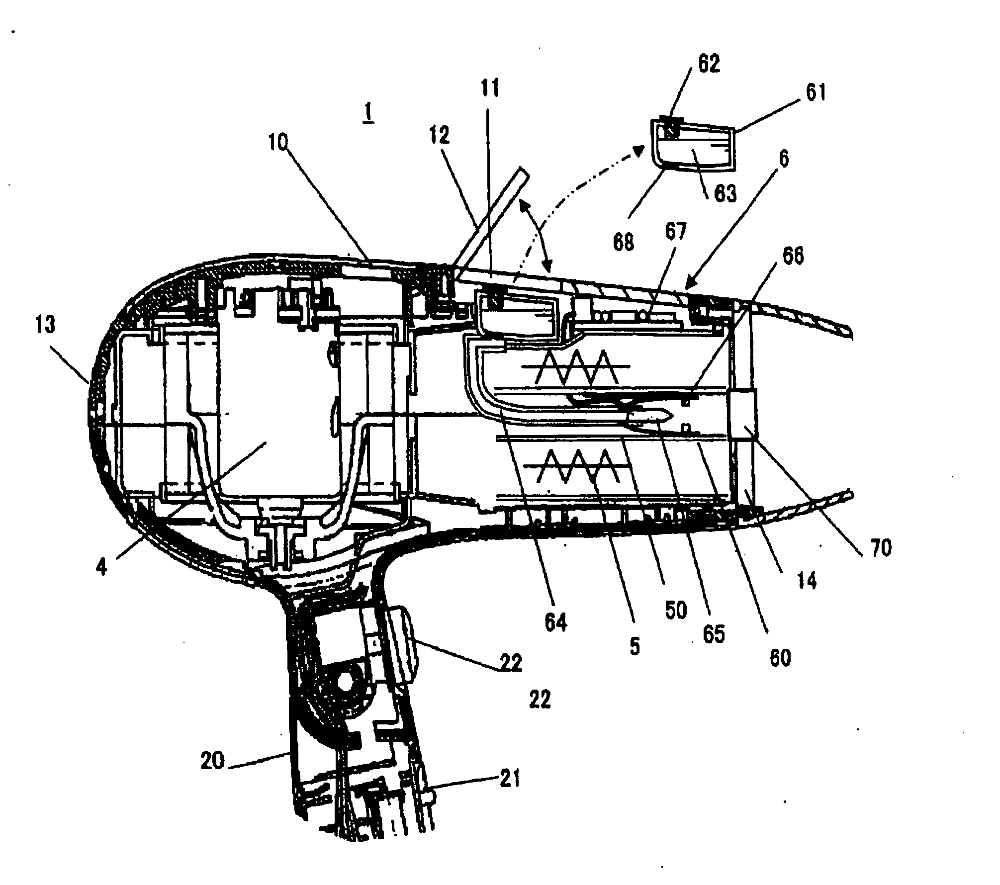
[0036] An electrostatic atomizing hairdryer 1 in accordance with a first embodiment of the present invention is described with reference to the figures. FIG. 1 is a sectional view showing a configuration of the electrostatic atomizing hairdryer 1 in accordance with the first embodiment.

[0037] The electrostatic atomizing hairdryer 1 (hereinafter, it is called merely “hairdryer 1”) is comprised of a main body 10, a grip 20 that is established to make predetermined angle for the main body 10, and so on. A blower 4 configured by a motor, a fan, and so on is provided in an inside of the main body 10 and in the vicinity of a junction between the main body 10 and the grip 20. An air suction opening 13 is formed on a rear end of the main body 10 (left end in the figure), and a grating is provided on the air suction opening 13 so that no finger or no extraneous material cannot be inserted for safety. A heating unit 5 comprised of a heater, and so on and an electrostatic atomizing unit 6 are...

second embodiment

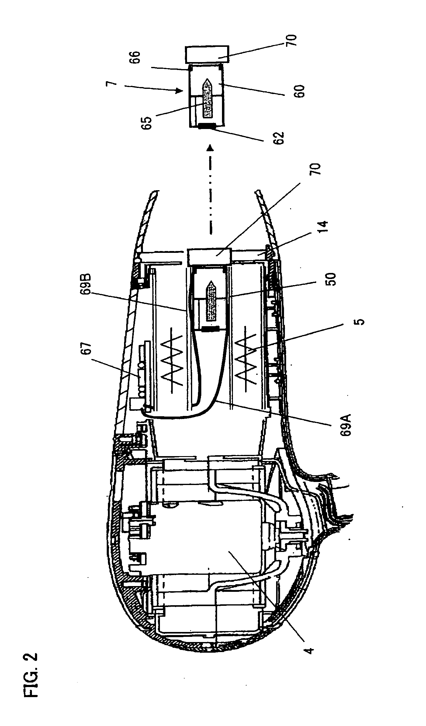
[0049] Subsequently, an electrostatic atomizing hairdryer 1 in accordance with a second embodiment of the present invention is described. FIG. 2 is a sectional view showing a configuration of the hairdryer 1 in accordance with the second embodiment. In the second embodiment, the electrode unit 60 and the tank 61 are unified, and it is detachable from the main body 10.

[0050] As shown in FIG. 2, the electrode unit 60 and the tank 61 are unified for constituting a cartridge 7 which is detachable from the main body 10. Furthermore, a member with the mist emitting opening 70 (hereinafter, abbreviated as mist emitting opening member 70), to which antistatic treatment is given, is attached to the cartridge 7 similar to the above first embodiment. Since the atomizing electrode 65 is provided for penetrating a partition wall between the electrode unit 60 and the tank 61, it is possible to omit the liquid feed pipe 64 and the liquid afflux path which are needed in the first embodiment. On th...

third embodiment

[0056] Subsequently, an electrostatic atomizing hairdryer 1 in accordance with a third embodiment of the present invention is described. FIG. 8 is a sectional view showing a configuration of the hairdryer 1 in accordance with the third embodiment. In the third embodiment, a part of the airflow generated by the blower 4 is introduced into an inside of the adiabator 50 so as to pass the airflow without being heated by the heating unit 5. Therefore, it is configured that the cold blast is generated inside the hot blast and the electrostatically atomized mist is further generated inside the cold blast, as shown in FIG. 9. Since the cold blast which is not heated by the heating unit 5 passes the outside of the electrode unit 60, it is possible to prevent the leakage of the liquid from the liquid feed pipe 64 due to expansion of the liquid corresponding to temperature rise by the hot blast, and to prevent the evaporation of the mist generated in the electrode unit 60.

[0057] Furthermore, ...


PUM


Abstract

In an electrostatic atomizing hairdryer, electrostatically atomized mist generated in an electrostatic atomizing unit is effectively scattered into airflow emitted from a main body of the hairdryer so that the mist can be sprayed to hair uniformly and a time necessary for treatment of hair can be shortened. A tank constituting the electrostatic atomizing unit is detachably provided on a portion in the vicinity of an outer periphery of the main body, and an electrode unit for generating the mist is provided in a path of airflow sucked in an inside of the main body so as to be insulated from heat of a heating unit by an adiabator. A mist emitting opening from which the mist is emitted is disposed on a plane substantially the same as and at substantially the center of an air exit opening of the main body. Thereby, the mist emitted from the mist emitting opening is effectively scattered into the airflow emitted from the air exit opening.

Description

BACKGROUND OF THE INVENTION [0001] 1. Field of the Invention [0002] The present invention relates to a hairdryer used for drying or setting hair by blowing warm blast and cold blast, and especially relates to an electrostatic atomizing hairdryer which can perform treatment of hair by emitting jet of mist electrostatically atomized, and relates to an electrostatic atomizer for generating mist by electrostatically atomizing a liquid. [0003] 2. Description of the Related Art [0004] An electrostatic atomization technique to let water of form of minute mist (hereinafter, it is called “mist”) scatter by applying high voltage on feed water field member as a capillary tube is conventionally known. For example, in Japanese Laid-Open Patent Publication No. 2002-151146, this electrostatic atomization technique is applied to a hairdryer to obtain advantageous effects for improving moisture-holding characteristic of hair and giving hair gathered up feeling and shine by spraying mist to hair. [00...

Claims


Application Information

Patent Timeline
IPC IPC(8): A45D20/12F26B21/06
CPCA45D19/16A45D20/12B05B5/1691A45D2001/008A45D20/50B05B5/001
Inventor MATSUI, YASUNORIIMAHORI, OSAMUAKISADA, SHOSUKEMIHARA, FUMIOSUGAWA, AKIHIDEHIRAI, TOSHIHISANAKAGAWA, TAKASHIKAWAI, KOZOKODAMA, NAOFUMIYAMAGUCHI, TOMOHIROTAKASHIMA, KIYOSHIKATAYAMA, KOUSUKEWATANABE, JUNICHI
Owner MATSUSHITA ELECTRIC WORKS LTD
Why Eureka
Try Eureka