Rip fence for a table saw

a table saw and rip fence technology, applied in the field of rip fences for table saws, can solve the problems of flawed workpieces that exhibit “burning”, workpieces are kicked back toward the tool operator, and the parallelism of the rip fence with the cutting plane of the saw blade can sometimes be compromised, so as to achieve the effect of promoting parallelism

Inactive Publication Date: 2006-03-30
ROBERT BOSCH GMBH +1
View PDF14 Cites 12 Cited by
  • Summary
  • Abstract
  • Description
  • Claims
  • Application Information

AI Technical Summary

Benefits of technology

[0005] The instant invention includes various embodiments of a device and method for promoting parallelism, or “trueness,” between a plane of a rotary cutting blade that is at a right angle to a surface of a table and a rip fence of a table saw assembly. Specifically, embodiments of the invention include a rip fence that may be zeroed at a predetermined location, such as when near or in abutment with a the rotary cutting blade, and then moved away from the rotary cutting blade for a predetermined distance such that the distance from a cutting surface of the rotary cutting blade as well as its orientation with respect to the rotary cutting blade may be determined. Preferably, a front and a rear end of the rip fence include a mechanism whereby the respective distances from the rotary cutting blade may be determined, and that even minute differences in the respective distances may be reconciled to promote trueness between the rip fence and the cutting surface of the rotary cutting blade.

Problems solved by technology

However, while conventional rip fences provide some adjustability with respect to a distance at which it is disposed from a cutting plane of the saw blade, the parallelism of the rip fence with the cutting plane of the saw blade can sometimes be compromised depending upon the particular design of the rip fence mechanism.
Unfortunately, lack of parallelism or “trueness” not only accounts for inaccurate and imprecise cutting, it may result in a flawed workpiece that exhibits “burning” as the saw blade cuts at an unintended angle.
Moreover, lack of parallelism may also result in a dangerous condition wherein the workpiece is kicked back toward the tool operator.

Method used


Image

  • Rip fence for a table saw
  • Rip fence for a table saw
  • Rip fence for a table saw

Examples


Embodiment Construction

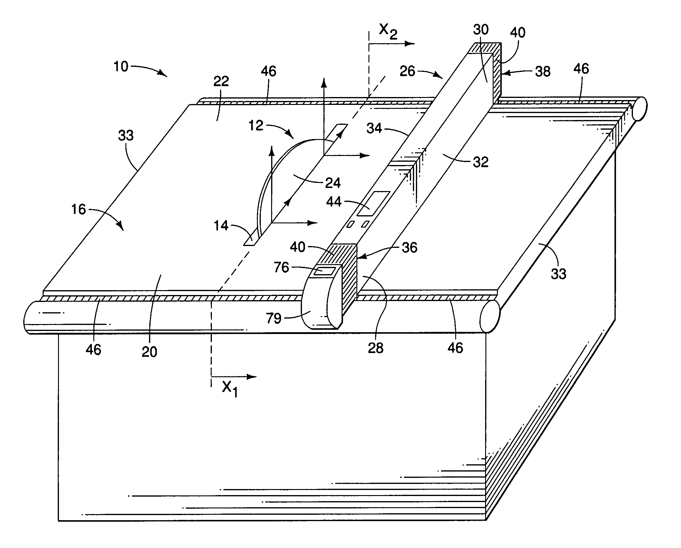
[0016] While it is contemplated that the invention may be used with a variety of conventional table saw assemblies, such as those manufactured under the SKIL and BOSCH brands by the S-B Power Tool Corporation of Chicago, Illinois, one exemplary table saw assembly, indicated generally at 10, is illustrated in FIG. 1 in connection with a first embodiment of the invention. According to the embodiment illustrated in FIG. 1, a rotary cutting blade 12 extends upwardly through a blade bracket 14, which is an elongated slot disposed in a generally middle portion of a table 16. A pair of miter gauge slots 18 (best shown in FIG. 2) are also preferably provided, one on each side of the blade bracket 14, and extending from a front end 20 of the table 16 to a rear end 22 of the table. While the rotary cutting blade 12 may be tiltable for miter cutting, a radial plane 24 of the rotary cutting blade 12 generally extends perpendicularly with respect to a plane of the table.

[0017] An elongated, gen...


PUM

PropertyMeasurementUnit
widthaaaaaaaaaa
widthsaaaaaaaaaa
lengthaaaaaaaaaa

Abstract

A power table saw of the type which has a generally rectangular table with front and rear end portions, a motor operatively coupled to drive a rotary cutting blade extending upwardly through a top of the table, the table saw including an elongated fence having front and rear end portions, and being configured to be laterally movable along the width of the table and be secured to the front and rear end portions of the table, front and rear releasable locking mechanisms operatively associated with the front and rear end portions of the fence for locking each end portion to the end portions of the table, and at least one positional sensor provided with each of the front and rear end portions of the fence for determining the lateral position of each end portion of the fence along the width of the table.

Description

BACKGROUND OF THE INVENTION [0001] Table saws are valuable tools used for a variety of tasks, such as cross-cutting wood and plastic, and ripping long boards into narrow strips. While there are a variety of table saw designs, most table saws include a circular saw blade mounted on an arbor that is turned by one or more belts that are driven by a motor. The saw blade extends through an opening in the surface of a saw table, on which surface the workpiece rests and is supported. The depth of cut is varied by adjusting the amount of the blade that extends above the table surface such that the higher the blade extends above the table, the deeper the cut that is made in the material. Angle of the cut with respect to the table surface is typically controlled by adjusting the angle of the arbor to which the blade is affixed. [0002] Additionally, table saws nearly always include a fence or guide that extends from a side of the table nearest the operator to a side furthest from the operator,...

Claims


Application Information

Patent Timeline
Patent Type & Authority Applications(United States)
IPC IPC(8): B26D1/00
CPCB27B27/02B23Q3/007Y10T83/04Y10T83/727Y10T83/76Y10T83/773Y10T83/857Y10T83/858
Inventor GRISWOLD, SCOTTRAMON, TAMSVETLIK, KENNETH N.TALESKY, MARK S.VORUGANTI, RAVIWOLF, BRADLEY
Owner ROBERT BOSCH GMBH
Why Eureka
Try Eureka