Rotary engine
a rotary engine and rotor technology, applied in the direction of liquid fuel engines, machines/engines, combination engines, etc., can solve the problems of 20° of contact angle between the inner circumferential contact wall, inability to maintain perfect air tightness, and inability to achieve perfect air tightness, improve sealing performance, and improve fuel combustion efficiency
- Summary
- Abstract
- Description
- Claims
- Application Information
AI Technical Summary
Benefits of technology
Problems solved by technology
Method used
Image
Examples
first embodiment
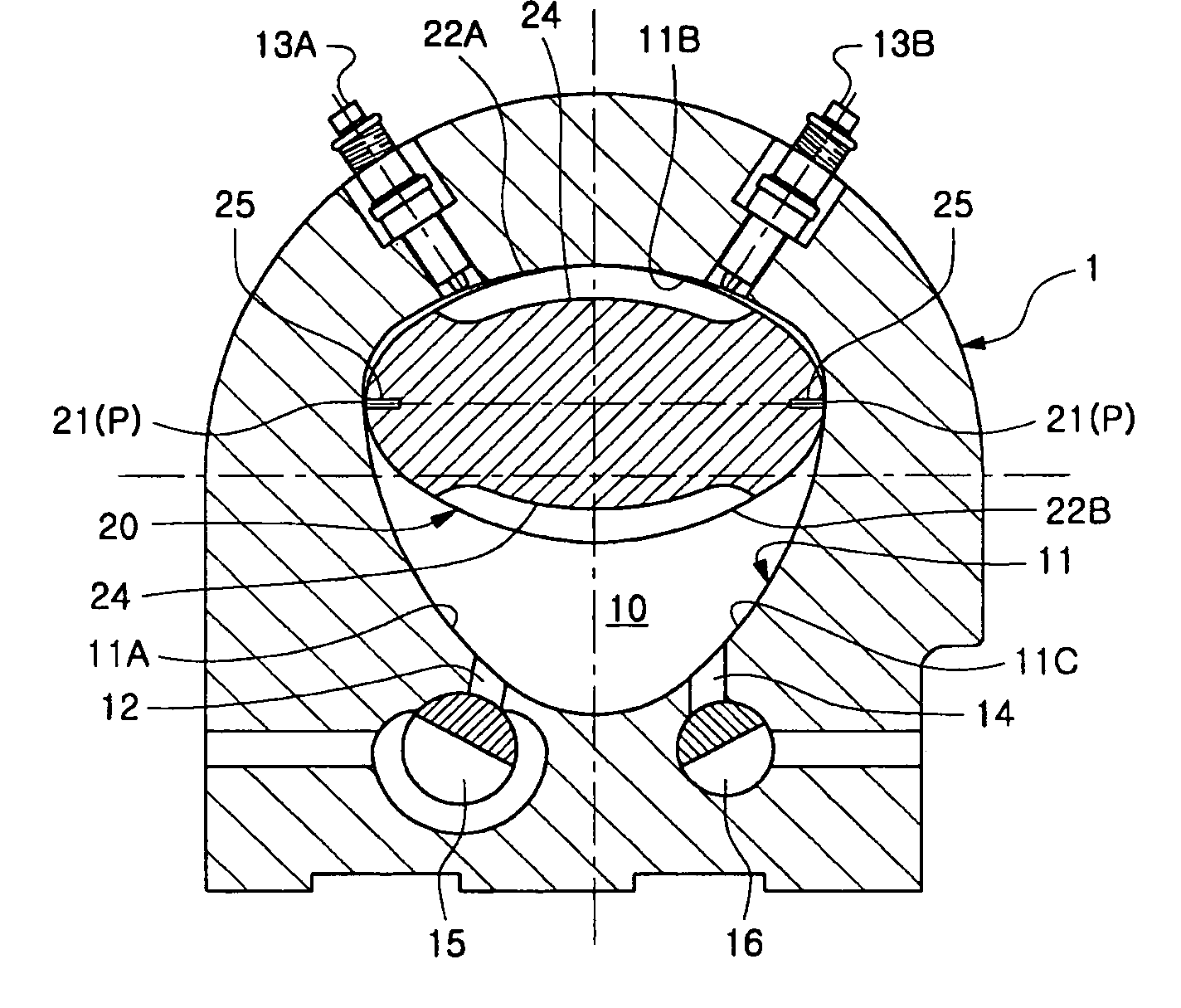
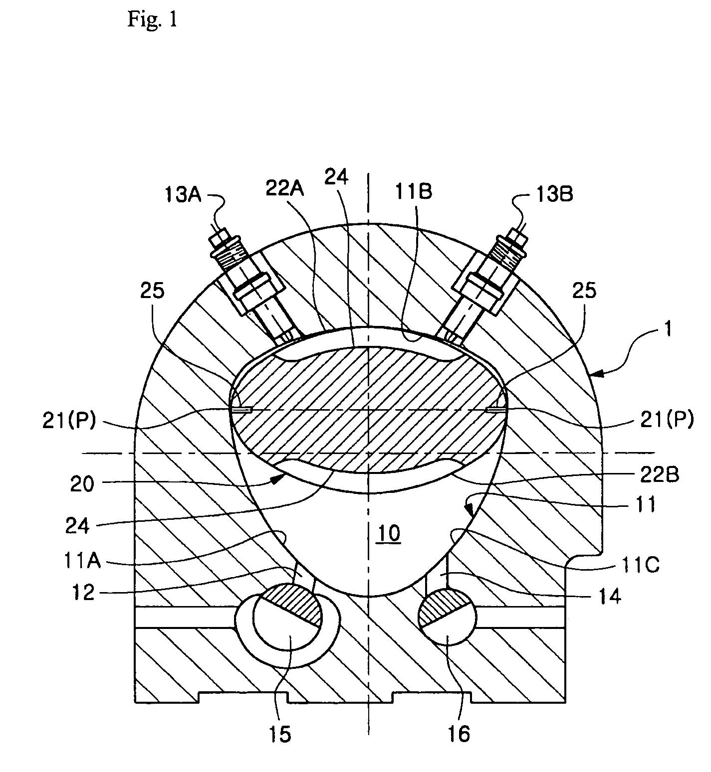
[0030]FIG. 1 is a schematic configuration diagram illustrating a rotary engine according to the present invention. As shown in FIG. 1, the rotary engine according to the present embodiment comprises a cylinder body 1 having a cylinder chamber 10, and a rotor 20, which is received in the cylinder chamber 10 to eccentrically rotate.
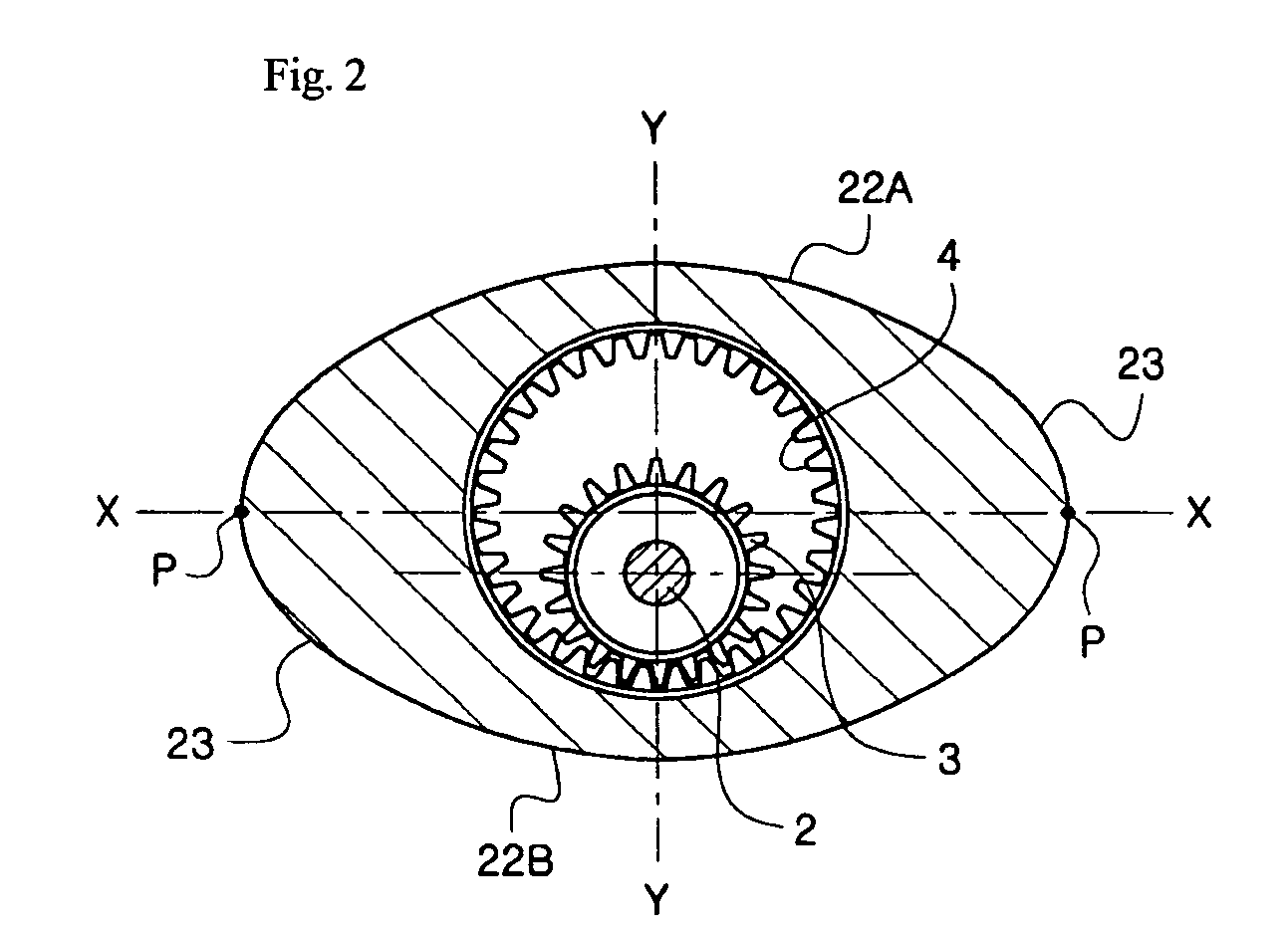
[0031] The rotor 20 has an elliptical shape, and is provided at opposite apexes P thereof in a direction of a major axis X-X with seal faces 21, which come into contact with an inner circumferential contact wall 11 of the cylinder chamber 10. The cylinder chamber 10 has the same shape as a specific curve which is described by the opposite apexes P when the rotor 20 eccentrically rotates. The inner circumferential contact wall 11 of the cylinder chamber 10 includes arcuate first to third sides 11A to 11C, and connecting portions between the respective edges of the first to third sides 11A to 11C are curved, whereby the inner circumferential contact wall 11 h...
second embodiment
[0051] The rotary engine according to the present invention comprises a cylinder body 101 having two cylinder units, i.e. first and second cylinder units 110 and 120, which are arranged in parallel to each other in an axial direction of an output shaft 102. The rotary engine further comprises a pair of rotors 20, which are received in the first and second cylinder units 110 and 120, respectively, to cross each other with a phase difference of 90°.
[0052] The first and second cylinder units 110 and 120 have superchargers 111 and 121, respectively. The superchargers 111 and 121 are located between the intake port 12 and the spark plug 13A of the respective cylinder chambers 10, i.e. at the first side 11A of the respective cylinder chambers 10. As shown in FIG. 5, the superchargers 111 and 121 are connected to each other through a bypass channel 113 provided in the cylinder body 101.
[0053] The superchargers 111 and 121 are provided with opening / closing valves 112 and 122, respectively....
third embodiment
[0086] With the supercharging means according to the present invention, the uncombusted gas, which leaks from between the inner circumferential contact wall 11 of the cylinder chamber 10 and the seal members 25 during the compression stroke and remains in the section A of the cylinder chamber 10, is charged into the supercharging chamber 210. After being temporarily stored in the supercharging chamber 210, the uncombusted gas is able to be returned from the supercharging chamber 210 into the cylinder chamber 10 during the intake stroke of the cylinder chamber 10. This effectively increases the intake amount of the gas mixture while preventing discharge of the uncombusted gas to the outside, thereby achieving an enhancement in generation of rotational power in an expansion stroke and preventing waste of fuel and air pollution.
[0087] In the preferred embodiments of the present invention as described above, the rotary engine is configured to have a single cylinder unit, two cylinder un...
PUM
 Abstract
Description
Claims
Application Information
 - R&D
- Intellectual Property
- Life Sciences
- Materials
- Tech Scout
- Unparalleled Data Quality
- Higher Quality Content
- 60% Fewer Hallucinations
Browse by: Latest US Patents, China's latest patents, Technical Efficacy Thesaurus, Application Domain, Technology Topic, Popular Technical Reports.
© 2025 PatSnap. All rights reserved.Legal|Privacy policy|Modern Slavery Act Transparency Statement|Sitemap|About US| Contact US: help@patsnap.com


