Centrifuge with combinations of multiple features

a technology of centrifuges and features, applied in centrifuges, separation processes, filtration separation, etc., can solve the problems of dense contaminants, clogging of rotating chambers with particulates or solids, and failure to remove light density contaminants by conventional processing methods, so as to prevent or reduce the compacting of more dense materials, reduce the friction effect of receptacle walls, and reduce effective frictional forces

Inactive Publication Date: 2006-03-30
PHASE
View PDF99 Cites 7 Cited by
  • Summary
  • Abstract
  • Description
  • Claims
  • Application Information

AI Technical Summary

Benefits of technology

[0014] One technical advantage of the present invention may include reducing friction effect of a receptacle wall with respect to movement of more dense material along the wall. Vibration in the receptacle may create a “slippery” wall effect thus reducing effective frictional forces imparted on more dense material against the walls. This “slippery” wall effect may cause more dense material to proceed along the wall to an associated opening for separation from a fluid medium.
[0015] Another technical advantage of the present invention includes preventing or reducing compacting of more dense material in a receptacle during increased de-watering. Vibration may cause more dense material to collect in the receptacle and move through an associated opening. A build up of such more dense material may clog the opening further compacting more dense material, which removes more clarified fluid. Vibrations may then cause the particle to breakup at a desired operating condition thus removing the de-watered more dense material from the receptacle.
[0016] A further technical advantage of the present invention may include varying the velocity of separation of more dense material in a fluid medium. Steep or shallow walls on an interior of a receptacle wall may create frictional forces as more dense material moves towards an associated opening. The frictional forces may vary depending upon the angle or slope of the receptacle walls. By increasing the angle or slope, such as adding a steep wall, more dense material may move more rapidly toward the associated opening. This may decrease desired separation caused by centrifugal force since less dense fluid may be carried out an associated opening along with more dense material. Providing a shallow sloped wall one or more interior surfaces of a receptacle allows frictional forces to slow the movement of more dense material, which permits additional removal of liquids such as water from more dense material as it moves more slowly along the walls of the receptacle towards the associated opening. Vibrational forces may be incorporated with these sloped walls to further aid in separation of more dense material from the fluid medium.
[0017] A further technical advantage of the present invention may include prevention of clogging of openings in a fluid separation wall. In some embodiments of the present invention, an anti-clogging projection may be placed in the opening to prevent clogging by the more dense particles. The anti-clogging projection may be formed within the inner surface of a nozzle to create a turbulent flow out of the nozzle. The turbulent flow may prevent blockage as the more dense particles exit the nozzle.
[0018] A further technical advantage of the present invention includes disrupting any cyclonic vorticity created in a void area of a receptacle. Placing an anti-vorticity projection in a receptacle may prevent formation of a cyclonic vorticity within the void area of the receptacle. Preventing this vorticity may enhance separation of the more dense particles from the fluid medium.

Problems solved by technology

Because of their relatively small size, many light density contaminants (e.g., microorganisms) have failed to be removed by conventional processing methods including fluid separation.
As more dense contaminants are extracted from the fluid medium, the openings formed in the wall that allow the more dense contaminants to be expelled from the rotating chamber may become clogged with particulate matter or solids.
Despite high centrifugal force, particulate matter may clog the openings and create a build up of relatively solid materials behind this “clog-point”.
Another problem may exist within the centrifuge due to the rotation of the chamber.
Some of the problems associated controlling the release of more dense contaminants through the opening include the direction of valve movement, the location of the valve members, and the location of the actuator for controlling the valve.

Method used


Image

  • Centrifuge with combinations of multiple features
  • Centrifuge with combinations of multiple features
  • Centrifuge with combinations of multiple features

Examples


Embodiment Construction

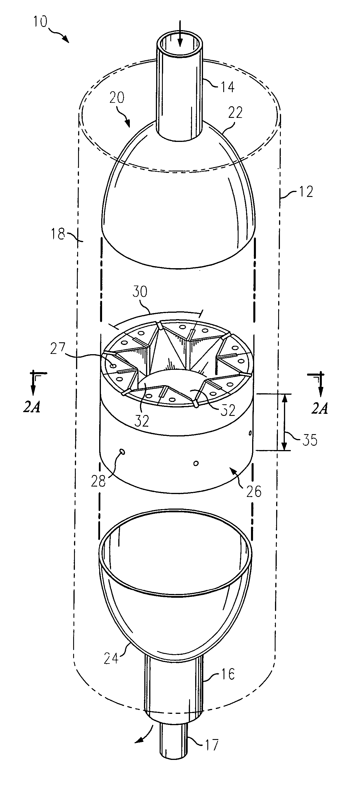
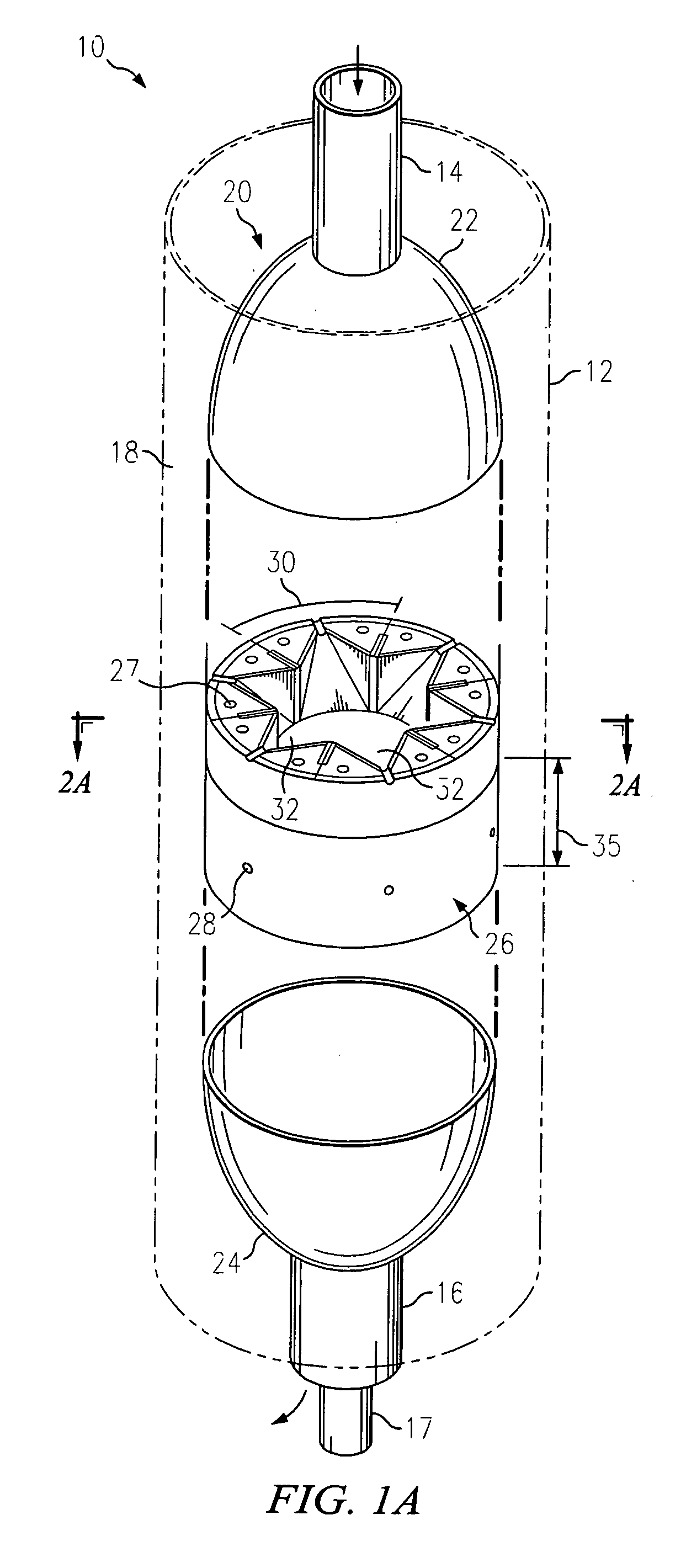
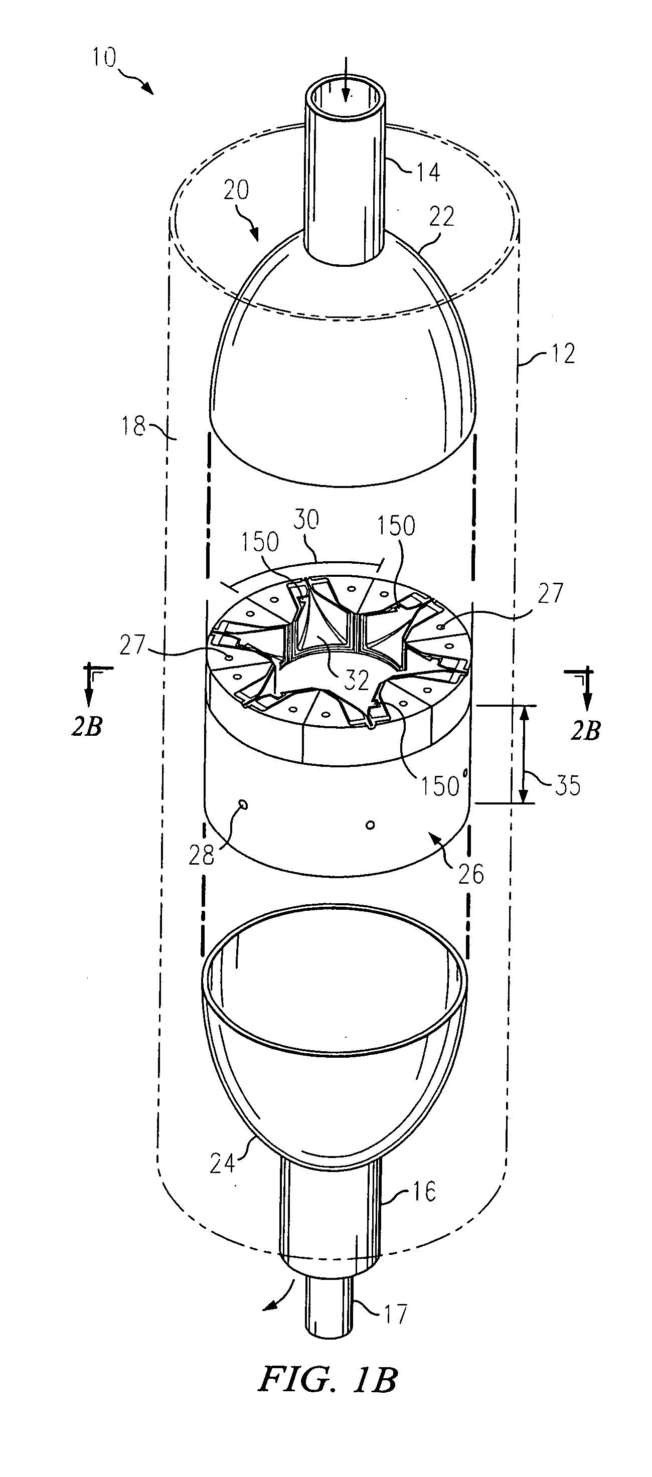
[0053] Preferred embodiments of the present invention and their advantages are best understood by reference to FIGS. 1 through 32 where like numbers are used to indicate like and corresponding parts.

[0054]FIGS. 1A, 1B and 1C illustrate schematic drawings showing isometric views with portions broken away of example embodiments of centrifuge 10. Centrifuge 10 may include centrifugal core 20 disposed within non-rotating outer sleeve 12. Centrifugal core 20 may include fluid medium inlet 14, clarified fluid outlet 16, and fluid separation wall 26. Fluid separation wall 26 may be encapsulated between first housing cover 22 and second housing cover 24.

[0055] Non-rotating outer sleeve 12 may form accumulation area or containment zone 18 between centrifugal core 20 and non-rotating outer sleeve 12. Accumulation area 18 may collect more dense particles and other contaminants that have been separated from the fluid medium and have passed through openings 28. As the more dense particles coll...


PUM

PropertyMeasurementUnit
frequencyaaaaaaaaaa
sizeaaaaaaaaaa
angle of slopeaaaaaaaaaa

Abstract

A centrifuge with combinations of multiple features is disclosed. In one aspect, a centrifuge for removing more dense material from a fluid medium includes a fluid separation wall placed within a sleeve. The fluid separation wall rotates around the axis of rotation. A receptacle aids in separation of the more dense material from the fluid medium. The receptacle defined in a part by a respective geometry and a respective shape. An opening extends from the void area to the outer surface to transport the more dense material to the containment zone. An excitation apparatus associated with the receptacle creates a vibration within the receptacle. The centrifuge may further include a valve ring including a valve orifice the valve ring having a first position which blocks the more dense material from exiting the receptacle and a second position that allows the more dense material to move into the containment zone.

Description

CROSS REFERENCE TO RELATED APPLICATION [0001] This application is a divisional of U.S. patent application Ser. No. 10 / 876,167 filed Jun. 24, 2004, and entitled “Centrifuge with Combinations of Multiple Features,” which claims priority to U.S. Provisional Patent Application Ser. No. 60 / 483,275 filed Jun. 25, 2003, the contents of which are hereby incorporated by reference.TECHNICAL FIELD OF THE INVENTION [0002] This disclosure relates in general to the field of centrifugal devices, and more particularly to a centrifuge having replaceable internal components with controlled discharge of dense material including a system and method for vibration in the centrifuge. BACKGROUND OF THE INVENTION [0003] Over the past several years, demand has increased for the efficient removal of contaminants from water supplies. Because of their relatively small size, many light density contaminants (e.g., microorganisms) have failed to be removed by conventional processing methods including fluid separat...

Claims


Application Information

Patent Timeline
Patent Type & Authority Applications(United States)
IPC IPC(8): C02F1/32B01D21/26B04B1/00B04B1/10B04B7/08B04B11/00
CPCB04B1/00B04B1/10B01D21/262B04B11/00B04B7/08
Inventor KIRKER, CURTISFULLER, BERKELEY F.
Owner PHASE
Why Eureka
Try Eureka