Rotor for an induction device

a technology of induction device and rotor core, which is applied in the direction of manufacturing cage rotors, magnetic circuit rotating parts, magnetic circuit shape/form/construction, etc., can solve the problems of premature malfunction of end rings, failure of motors, and lessening of performance, so as to facilitate electrical communication, improve mechanical integrity and electrical communication, and increase the mechanical integrity of the rotor core

Inactive Publication Date: 2006-03-30
RELIANCE ELECTRIC TECH
View PDF9 Cites 13 Cited by
  • Summary
  • Abstract
  • Description
  • Claims
  • Application Information

AI Technical Summary

Benefits of technology

[0006] According to one exemplary embodiment, the present invention provides a rotor for an electric motor. The exemplary rotor includes a rotor core having a generally circular cross-section and a series of rotor slots extending through the core in a direction generally transverse to the cross-section. The exemplary rotor also includes a pair of end members disposed at opposite ends of the rotor core. Each end member has a series of end slots that cooperate with the rotor slots to form rotor channels that extend through the rotor core and the end members. The rotor channels are configured to support electrically conductive members, which each include an interior portion disposed in the rotor channel and oblique portions that extend beyond the rotor channel. In the exemplary rotor, the oblique portions at least partially secure the end members to the rotor core, and the end members facilitate electrical communication between the electrically conductive members. By way of example, the oblique portions and the end members may be fused to one another to improve the mechanical integrity and electrical communicativeness between the two members.
[0007] In accordance with another embodiment, the present invention provides an exemplary process for fabricating a rotor for an electric motor. The exemplary process includes the act of aligning a seri...

Problems solved by technology

For example, if not properly accounted for, the centripetal and centrifugal forces developed in the end ring may cause the end ring to prematurely malfunction.
Moreover, centripetal and centrifugal forces may, over time, negatively...

Method used


Image

  • Rotor for an induction device
  • Rotor for an induction device
  • Rotor for an induction device

Examples


Embodiment Construction

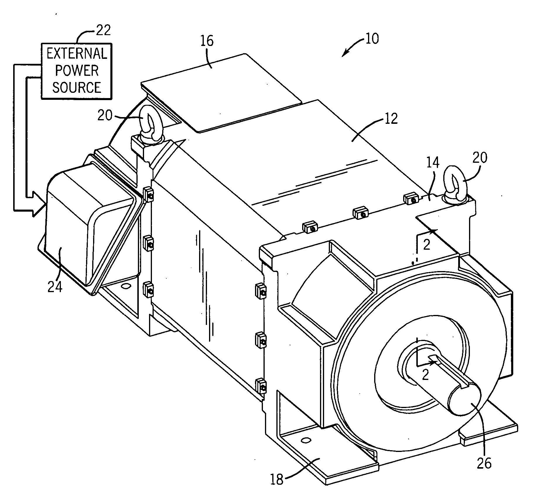
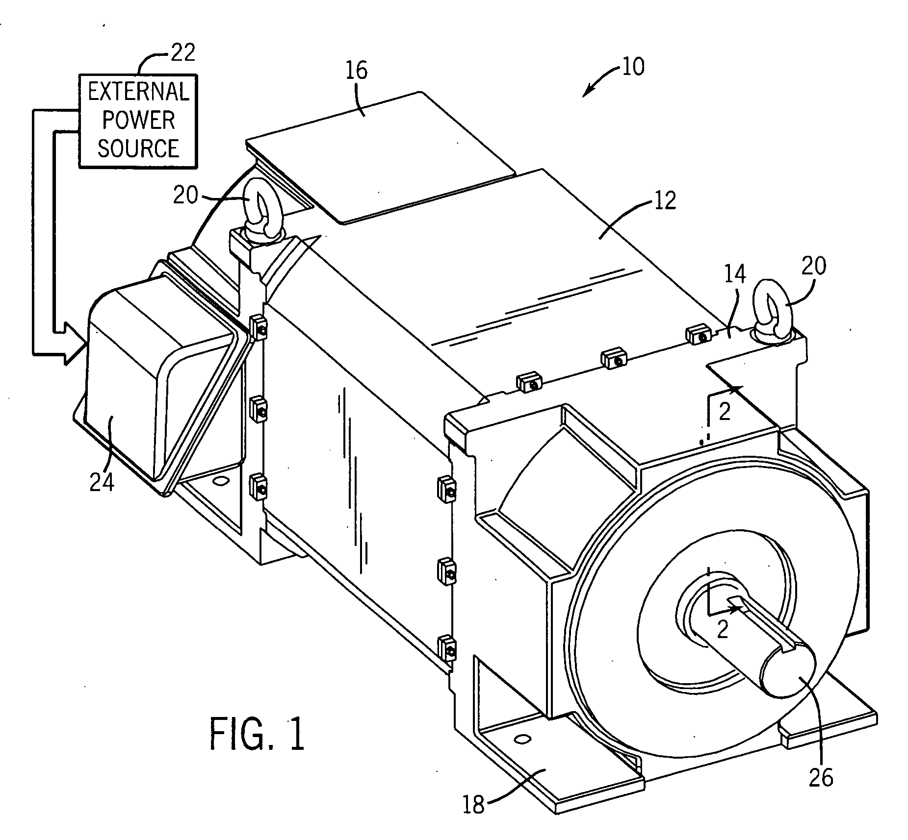
[0021] As discussed in detail below, embodiments of the present invention provide apparatus and methods for rotor construction for induction motors. Although the following discussion focuses on induction motors, the present invention also affords benefits to a number of applications in which the rotor integrity is a concern. Indeed, the present technique is applicable to any number of devices, such as induction generators, to name but one additional example. Accordingly, the following discussion provides exemplary embodiments of the present invention and, as such, should not be viewed as limiting the appended claims to the embodiments described.

[0022] As a preliminary matter, the definition of the term “or” for the purposes of the following discussion and the appended claims is intended to be an inclusive “or.” That is, the term “or” is not intended to differentiate between two mutually exclusive alternatives. Rather, the term “or” when employed as a conjunction between two element...


PUM


Abstract

According to one embodiment, the present invention provides a rotor assembly. The exemplary rotor assembly includes a plurality of rotor laminations, which cooperate to form a rotor core, capped at each end by end members. Extending through the rotor core and the end members, a plurality of rotor channels is configured to receive electrically conductive members therethrough. Each of the electrically conductive members has external portions, which extend beyond the rotor channel, and an interior portion that is housed within the rotor channel. By flexing the external portions, a compression force that secures the laminations and the end members with respect to one another may be provided. Advantageously, the external portions may be fused to one another and/or to the end members. As one example, the external portions may be fused through the introduction of a molten metal into the end member. Advantageously, fusing of the external portions to the end members and/or one another increases the mechanical integrity of the rotor and provides for good electrical communicativeness between the conductive members, for example.

Description

BACKGROUND [0001] The present invention relates generally to the field of electric motors and, particularly, to rotors for induction devices, such as a fabricated squirrel cage rotor, for example. [0002] Electric motors of various types are commonly found in industrial, commercial and consumer settings. In industry, such motors are employed to drive various kinds of machinery, such as pumps, conveyors, compressors, fans and so forth, to mention only a few. Conventional alternating current (ac) electric motors may be constructed for single- or multiple-phase power, and are typically designed to operate at predetermined speeds or revolutions per minute (rpm), such as 3600 rpm, 1800 rpm, 1200 rpm, and so on. Such motors generally include a stator comprising a multiplicity of windings surrounding a rotor, which is supported by bearings for rotation in the motor frame. Typically, the rotor comprises a core formed of a series of magnetically conductive laminations arranged to form a lamin...

Claims


Application Information

Patent Timeline
IPC IPC(8): H02K9/20H02K9/00
CPCH02K17/16H02K15/0012
Inventor NARAYANAN, RAJMOHANSHOYKHET, BORIS A.DRISCOLL, DAVID I.
Owner RELIANCE ELECTRIC TECH
Why Eureka
Try Eureka