Floor beam support assembly, system, and associated method

a technology for supporting systems and beams, applied in girders, joists, transportation and packaging, etc., can solve the problems of poor electrical conductivity of composite materials, current return networks and grounding problems of composite materials, etc., to reduce the incidence of misalignment and installation time, and facilitate electrical communication.

Active Publication Date: 2017-04-04
THE BOEING CO
View PDF25 Cites 0 Cited by
  • Summary
  • Abstract
  • Description
  • Claims
  • Application Information

AI Technical Summary

Benefits of technology

[0008]Embodiments of the invention may address at least some of the above needs and achieve other advantages by providing an assembly, a system, and a method for supporting floor beams and providing a current return network and grounding within a structure. Generally, embodiments of the present invention include floor beams supported by brackets secured to a structure, such as an aircraft structure. In addition, conductive elements are employed that facilitate electrical communication with the support brackets, such that current return networks and grounding may be maintained despite the presence of one or more composite materials that comprise the floor beam and / or structure. Fasteners need not necessarily be used to support the floor beams, which may reduce the incidence of misalignment and the installation time.

Problems solved by technology

The use of composite material creates unique design, integration, and assembly issues that would normally not be problematic with respect to metallic materials.
In particular, composite materials present issues with respect to current return networks and grounding.
However, composite materials typically have poor electrical conductivity and, therefore, require the installation of secondary metallic structures for current grounding and return network.

Method used


Image

  • Floor beam support assembly, system, and associated method
  • Floor beam support assembly, system, and associated method
  • Floor beam support assembly, system, and associated method

Examples


Embodiment Construction

[0020]The present invention now will be described more fully hereinafter with reference to the accompanying drawings, in which some, but not all embodiments of the invention are shown. Indeed, the invention may be embodied in many different forms and should not be construed as limited to the embodiments set forth herein; rather, these embodiments are provided so that this disclosure will satisfy applicable legal requirements. Like numbers refer to like elements throughout.

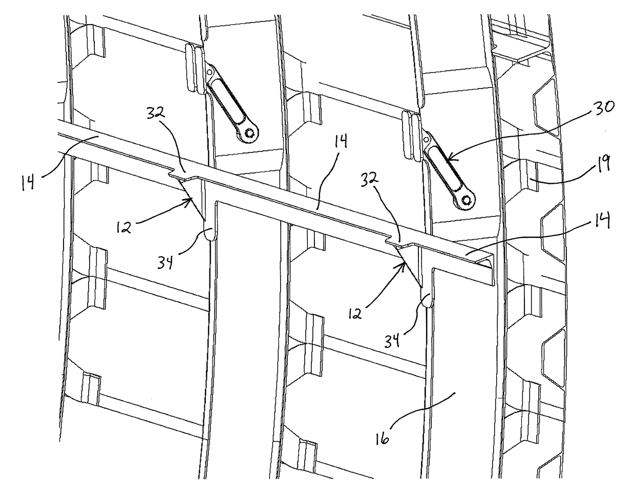
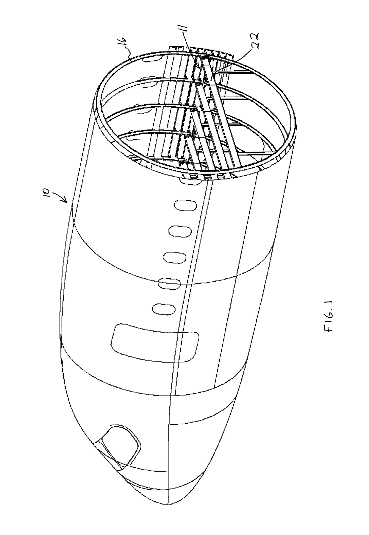
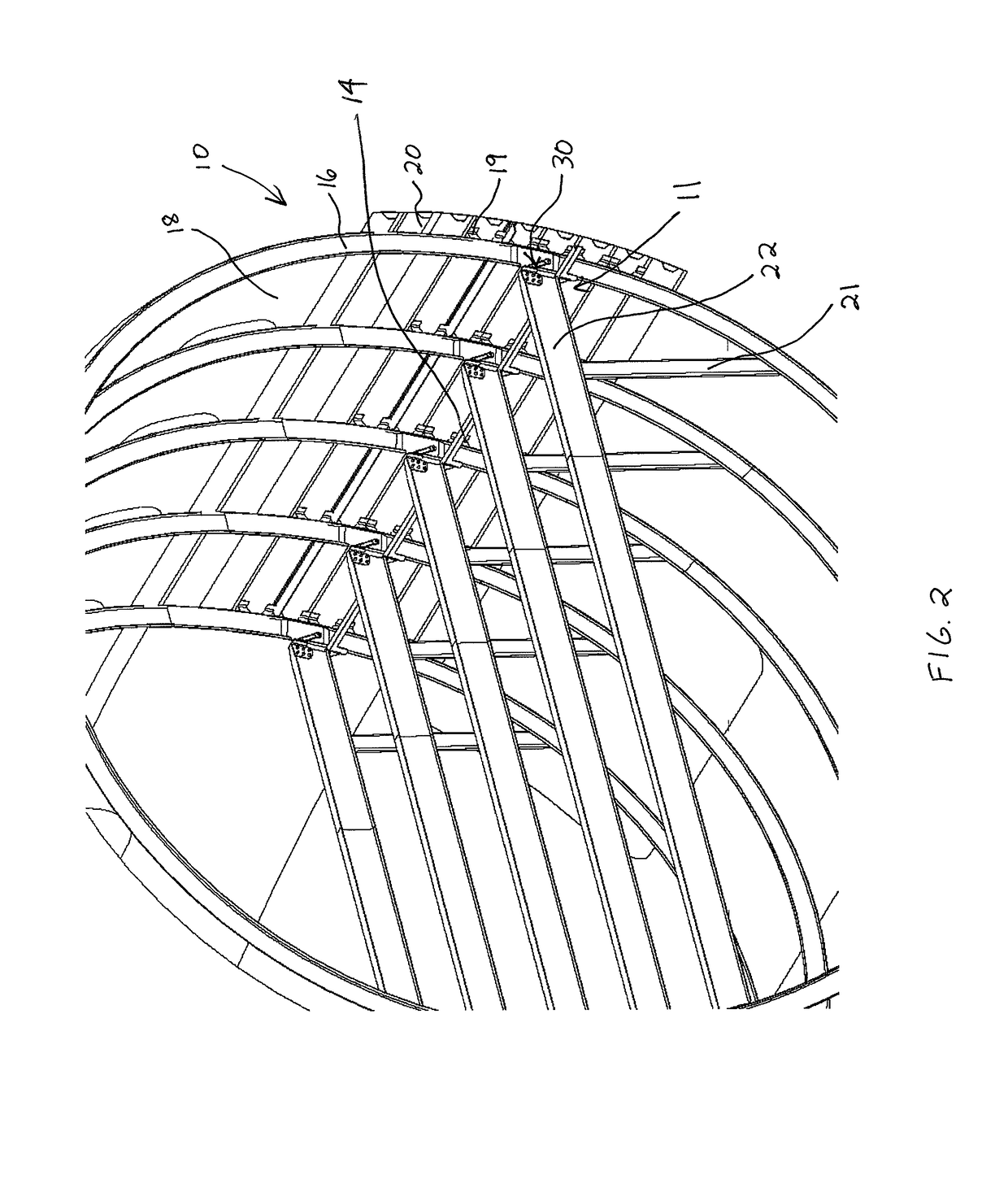
[0021]Referring now to the drawings and, in particular to FIG. 1, there is shown a system 10 for supporting a floor beam assembly 11 and providing grounding and current return networks within an aircraft structure according to one embodiment of the present invention. In particular, the floor beam assembly includes a plurality of support brackets 12 and conductive elements 14 that extend in a fore-aft direction along the structure. The conductive elements 14 provide a conductive current path for grounding and curren...


PUM


Abstract

A floor beam assembly, system, and method for supporting floor beams within a structure are provided. According to one embodiment, a floor beam assembly for installing a floor beam within a structure is provided. The assembly includes at least one floor beam, wherein at least a portion of each floor beam comprises a composite material. The assembly also includes at least one support bracket attached to a structure, wherein each support bracket is configured to support at least a portion of a floor beam thereon. In addition, the assembly includes at least one conductive element extending from the at least one support bracket and configured for electrically communicating with the at least one support bracket.

Description

BACKGROUND OF THE INVENTION[0001]1) Field of the Invention[0002]Embodiments of the present invention relate to floor beam supports and, more particularly, to apparatus, systems, and methods for supporting floor beams and providing a current return network and grounding within a structure.[0003]2) Description of Related Art[0004]The floor of an aircraft is typically built up from a series of spaced apart transverse floor beams that span across oval hoop frames to form the structural framework for the aircraft fuselage. The floor beams are usually aluminum and are individually attached with fasteners at each end to the hoop frames via a lap joint. The joint formed between the floor beam and the hoop frame bears the transverse and shear loads applied to the floor beam. Loads applied in the fore and aft direction are bore by longitudinal shear trusses between the floor and the fuselage wall.[0005]Current techniques for joining the floor beams and hoop frames require precise installation...

Claims


Application Information

Patent Timeline
Patent Type & Authority Patents(United States)
IPC IPC(8): B64C1/18E04C3/04
CPCB64C1/18E04C2003/0452
Inventor WOOD, JEFFREY H.SAFF, CHARLES R.
Owner THE BOEING CO
Why Eureka
Try Eureka