Self-sealing flow frame for flow battery stack

a flow battery and self-sealing technology, applied in the direction of fuel cell details, electrochemical generators, electrochemical stream management, etc., can solve problems such as obstruction of fluid flow, and achieve the effect of facilitating electrical communication

Active Publication Date: 2017-08-08
CONCURRENT TECH
View PDF5 Cites 0 Cited by
  • Summary
  • Abstract
  • Description
  • Claims
  • Application Information

AI Technical Summary

Benefits of technology

[0016]The first frame component and second frame component are configured to be placed in serial construction within a device having constituent parts and a fluid such that the first and second frame components sandwich the constituent parts and contain the fluid. The first and second seal profiles form a tessellation engagement with the constituent parts when the first and second frame components are compressively secured to each other. This tessellation engagement forms a fluid seal to prevent exfiltration or leakage of the fluid while the device is subject to positive pressure. Each of the inlet and outlet ports facilitate fluid communication with an ancillary manifold of the device. The first and second connector tabs facilitate electrical communication between the device and an ancillary load.
[0020]It is a further object of the present invention to configure the tongue-and-groove arrangement to enable the tessellation engagement to create a fluid seal when the first frame component and second frame component are used to compress the constituent parts, such that the first and second frame components sandwich the constituent parts and contain the fluid of the device even when that device is subject to a positive pressure, thereby eliminating the need for O-rings, gaskets, or other sealing devices and sealants.
[0023]It is a further object of the present invention to provide a least one of the first frame component and second frame component with at least one connector tab to facilitate electrical communication between the device and an ancillary load.
[0024]It is a further object of the present invention to provide fastening apertures such that torqueing fasteners applied through the fastening apertures enables the tessellation engagement to form an adequate and continuous seal about the perimeter of the seal profile.

Problems solved by technology

As the first and second frame components are advanced towards each other and compress the constituent parts of the cell, the tongue-and-groove configurations of the half-cell plates engage, which creates an obstruction to fluid flow due to the tessellation of the engagement.

Method used


Image

  • Self-sealing flow frame for flow battery stack
  • Self-sealing flow frame for flow battery stack
  • Self-sealing flow frame for flow battery stack

Examples


Embodiment Construction

[0035]The following description is of an embodiment presently contemplated for carrying out the present invention. This description is not to be taken in a limiting sense, but is made merely for the purpose of describing the general principles and features of the present invention. The scope of the present invention should be determined with reference to the claims.

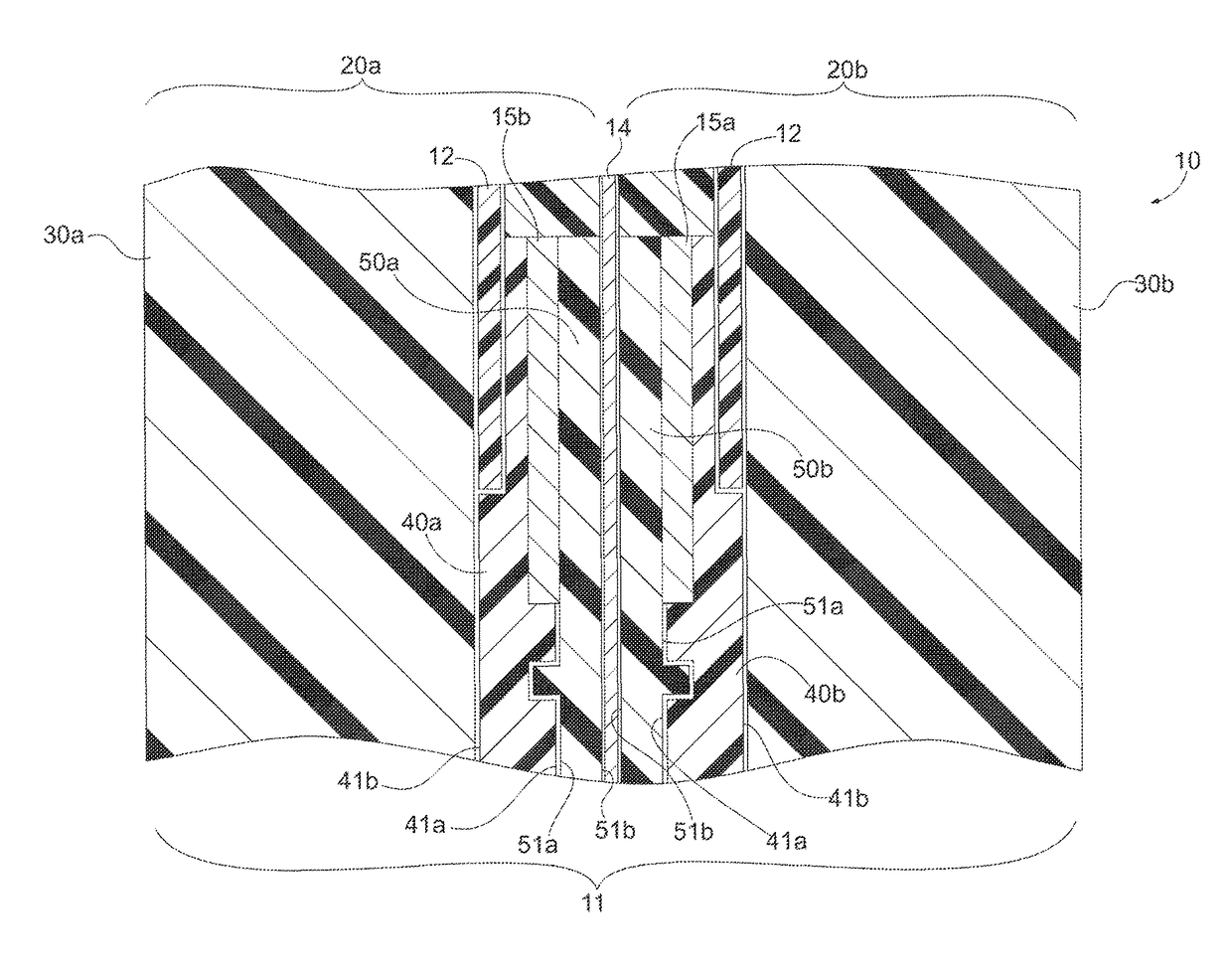
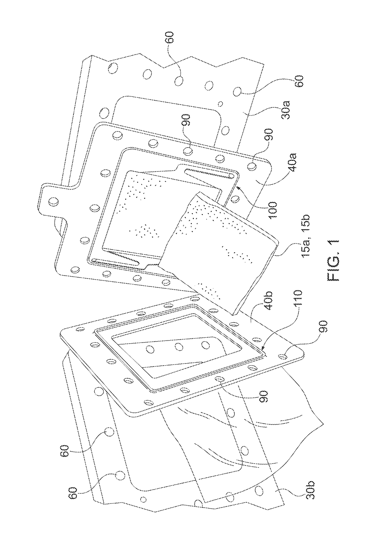
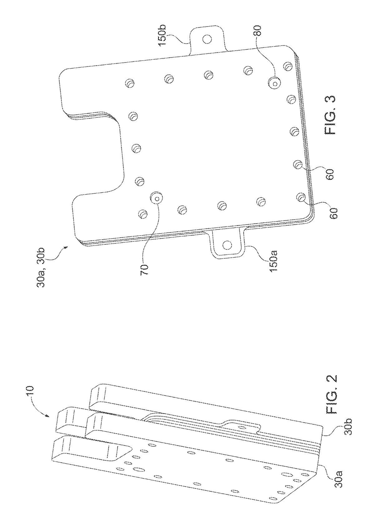
[0036]Referring now to FIGS. 1-6, views of the self-sealing flow frame 10 separated into its component parts and in assemblage, in accordance with a preferred embodiment, are disclosed. The self-sealing flow frame 10 is a framework that is intended to be used within a flow battery stack 11 (see FIG. 5); however, the self-sealing flow frame 10 is certainly not limited to such application. The self-sealing flow frame 10 exploits a tongue-and-groove configuration when sandwiching and compressing component parts of a device to contain fluids within that device without the need for separate and additional seals or gaskets; the...


PUM

PropertyMeasurementUnit
widthaaaaaaaaaa
widthaaaaaaaaaa
perimeteraaaaaaaaaa

Abstract

A self-sealing flow frame is provided having a first frame component and a second frame component. Each frame component is provided with a tongue-and-groove configuration that when assembled forms a tessellation engagement, which creates the seal. When each frame component is assembled into a flow frame, with the inner surfaces facing towards each other, the tongue-and-groove arrangements create a seal profile that circumscribe constituent parts of a device within which the self-sealing flow frame is being employed. As the frame components are compressively secured and fastened together, a tessellation engagement of the seal profile forms the fluid seal. Fluids of the device are prevented from exfiltrating the device, and are contained within the self-sealing flow frame by the fluid seal.

Description

CROSS-REFERENCE TO RELATED APPLICATIONS[0001]This patent application claims the benefit of U.S. Provisional Patent Application No. 62 / 030,712, filed on Jul. 30, 2014, which is hereby incorporated by reference in its entirety.FIELD OF THE INVENTION[0002]The present invention is directed generally towards a self-sealing framework for a fluid-containing apparatus and, more particularly, directed towards a self-sealing flow frame for a flow battery stack containing electrolyte fluids.BACKGROUND OF THE INVENTION[0003]A flow battery system is a rechargeable fuel cell exploiting the fluid dynamics, kinetics, and chemical potential properties of fluids containing electroactive elements (i.e., electrolytes) to convert chemical energy to electrical energy. The electrolytes typically comprise a catholyte fluid and an anolyte fluid, where each are stored in separate electrolyte tanks. At least one pump for each tank, directs the electrolytes from the electrolyte tanks and into a cell stack (com...

Claims


Application Information

Patent Timeline
Patent Type & Authority Patents(United States)
IPC IPC(8): H01M8/02H01M8/0276H01M8/04276H01M8/04H01M8/00H01M8/18H01M8/0273H01M8/0284
CPCH01M8/0273H01M8/006H01M8/0276H01M8/04276H01M8/188H01M8/0284Y02E60/528Y02E60/50
Inventor MCCLUSKEY, MICHEL J.GOVER, JR., JOHN ELLSWORTHTIPTON, BRYAN P.WEAVER, KEVIN ANTHONYKRONICK, JENNIFER LYNEBERKEY, DAVID B.MARKIEWICZ, DANIEL R.
Owner CONCURRENT TECH
Why Eureka
Try Eureka