Bonded rotor laminations

a rotor and rotor technology, applied in the direction of synchronous motors, dynamo-electric machines, magnetic circuit shapes/forms/construction, etc., can solve the problems of motor malfunction, difficult operation of motors at the speed corresponding to the first natural frequency, and lessen the performance of motors, etc., to facilitate the operation of rotors, increase the stiffness of rotor cores, and increase the stiffness of rotor assemblies

Inactive Publication Date: 2006-03-30
RELIANCE ELECTRIC TECH
View PDF8 Cites 31 Cited by
  • Summary
  • Abstract
  • Description
  • Claims
  • Application Information

AI Technical Summary

Benefits of technology

[0008] According to an exemplary embodiment, the present technique provides a rotor lamination for a motor rotor. The rotor lamination has an outer periphery that defines a generally circular lamination cross-section and an inner periphery that defines a central aperture configured to receive a rotor shaft therethrough. The exemplary lamination also has first and second end surfaces that extend from the outer periphery to the inner periphery and that are generally parallel to one another. Extending between the first and second end surfaces are a plurality of enclosed rotor-slots that are disposed concentrically about the central aperture. These rotor-slots extend generally transverse to the lamination cross-section. Additionally, the exemplary lamination has a bonding agent that is disposed on at least one of the first and second end surfaces. Advantageously, the bonding agent increases the stiffness of a rotor core formed of the exemplary lamination.
[0009] In accordance with another embodiment, the present technique provides a rotor for use in an electric motor. The rotor comprises a rotor core formed of a plurality of rotor laminations stacked with respect to one another. The rotor laminations cooperate to form enclosed rotor-slots and a central aperture that extend through the rotor core generally transverse to the rotor core's cross-section. The exemplary rotor also includes a rotor shaft disposed in the shaft chamber and a plurality of electrically conductive members disposed in the rotor channels. To increase the stiffness of the rotor assembly, a bonding agent located between at least one pair of adjacent rotor laminations is configured to bond the at least one pair of adjacent rotor laminations to one another. Advantageously, bonding of the rotor laminations facilitates operation of the rotor at higher speeds, i.e., high-speed operation.

Problems solved by technology

Indeed, resonance in the motor can lessen performance of the motor and, in certain instances, lead to a malfunction of the motor.
For example, if the stiffness of the rotor is not sufficient, the first natural frequency of variable speed motor may be below the maximal operational frequency, and, as such, difficulties in operating the motor at a speed corresponding to the first natural frequency often arise.
Accordingly, traditional rotors present inconsistencies with respect to stiffness of the rotor assembly, because of the uncertainty of the bending stiffness of the lamination stack.
Unfortunately, the inconsistencies in the stiffness of the rotor hinder accurate modeling of the rotor assembly.
That is to say, an inconsistency in the stiffness of the rotor impedes accurate prediction of the rotor's dynamic behavior.
Furthermore, traditional rotors present inconsistencies with respect to stiffness of the rotor assembly, because of the uncertainty of the bending stiffness of the lamination stack.
Unfortunately, these inconsistencies in the stiffness of the rotor hinder accurate modeling of the rotor assembly.
That is to say, inconsistencies in the stiffness of the rotor impeded accurate prediction of the rotor's dynamic behavior.

Method used


Image

  • Bonded rotor laminations
  • Bonded rotor laminations
  • Bonded rotor laminations

Examples


Embodiment Construction

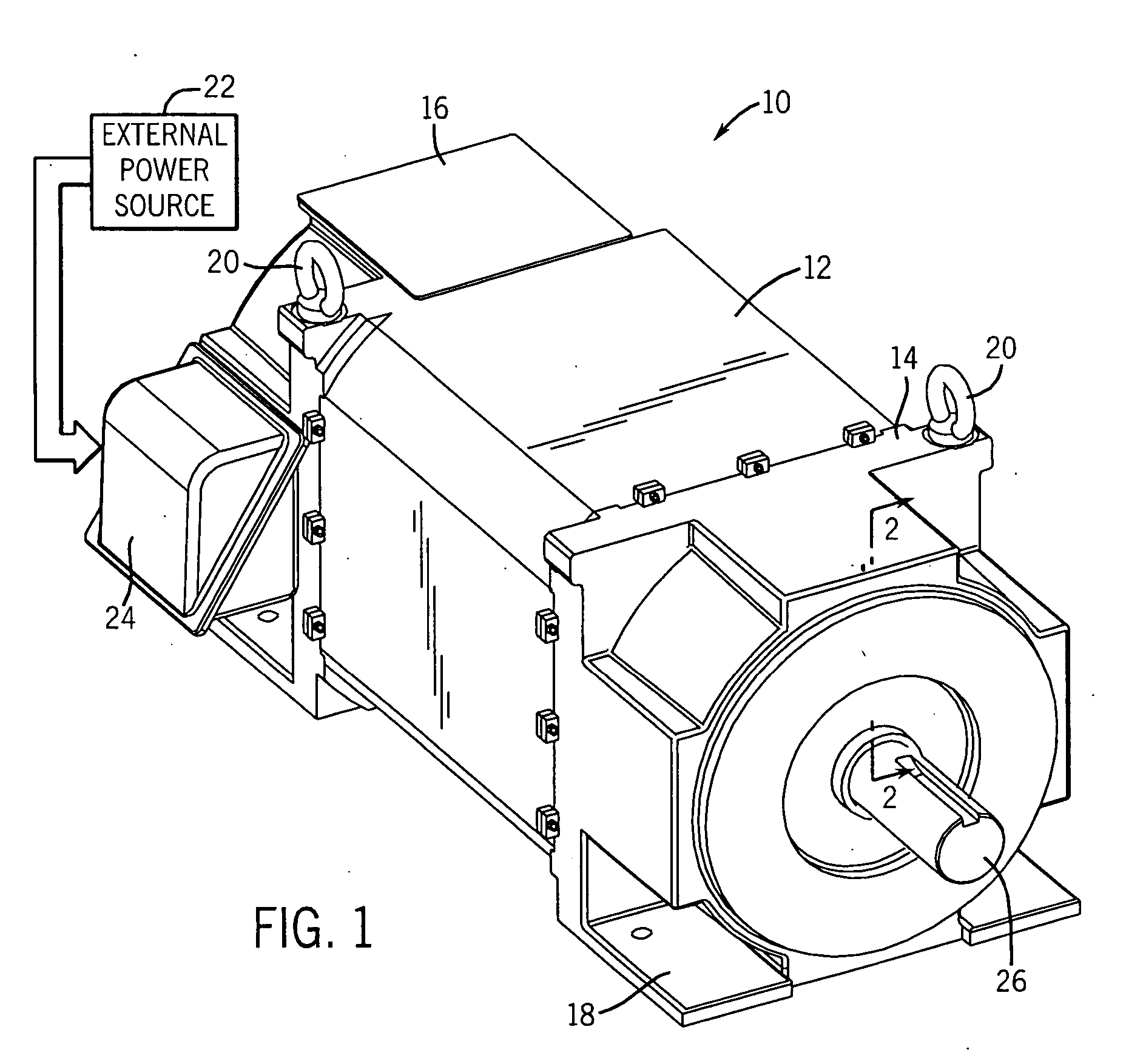
[0018] As discussed in detail below, embodiments of the present technique provide apparatus and methods for rotors and rotor construction. Although the following discussion focuses on induction motors, the present technique also affords benefits to a number of applications in which the rotor integrity is a concern. Indeed, the present technique is applicable to any number of induction motor and generators as well as non-induction based motors and generators. Accordingly, the following discussion provides exemplary embodiments of the present technique and, as such, should not be viewed as limiting the appended claims to the embodiments described.

[0019] Additionally, as a preliminary matter, the definition of the term “or” for the purposes of the following discussion and the appended claims is intended to be an inclusive “or.” That is, the term “or” is not intended to differentiate between two mutually exclusive alternatives. Rather, the term “or” when employed as a conjunction betwe...


PUM


Abstract

In accordance with an exemplary embodiment, the present technique provides a rotor assembly formed of a plurality of rotor laminations that are bonded to one another. Specifically, the rotor laminations are bonded to one another via a bonding agent disposed between end surfaces of adjacent rotor laminations. Advantageously, the bonding of the rotor laminations increases the overall stiffness of the rotor assembly, thereby facilitating high-speed operation. Moreover, the bonding of the rotor laminations increases the consistency in construction of the rotor assembly, thereby facilitating more accurate modeling of the rotor assembly.

Description

BACKGROUND [0001] The present technique relates generally to the field of electric motors and, particularly, to rotors for induction motors, such as a squirrel cage rotor, for example. [0002] Electric motors of various types are commonly found in industrial, commercial, and consumer settings. In industry, such motors are employed to drive various kinds of machinery, such as pumps, conveyors, compressors, fans and so forth, to mention only a few. Conventional alternating current (ac) electric motors may be constructed for single- or multiple-phase power, and are typically designed to operate at predetermined speeds or revolutions per minute (rpm), such as 3600 rpm, 1800 rpm, 1200 rpm, and so on, or for the continuously changing speed within the certain speed range. The latter is called variable speed operation. Such motors generally include a stator comprising a multiplicity of windings surrounding a rotor, which is supported by bearings for rotation in the motor frame. Typically, th...

Claims


Application Information

Patent Timeline
Patent Type & Authority Applications(United States)
IPC IPC(8): H02K17/16H02K17/22H02K19/14
CPCH02K17/16H02K15/12
Inventor SHOYKHET, BORIS A.
Owner RELIANCE ELECTRIC TECH
Why Eureka
Try Eureka