Eureka AIR delivers breakthrough ideas for toughest innovation challenges, trusted by R&D personnel around the world.

Motor apparatus and optical scanning apparatus, each with feedback control of drive load

Inactive Publication Date: 2006-03-30
CANON KK
View PDF11 Cites 14 Cited by
  • Summary
  • Abstract
  • Description
  • Claims
  • Application Information

AI Technical Summary

Benefits of technology

[0011] In the construction of a motor apparatus of the present invention wherein one of the magnetic sensor and the magnet is fixed to the output shaft of the motor, or the rotational axis portion of the load on the side opposite to the side of the motor with the load interposed therebetween, it is possible to dispose the magnetic sensor at a location, on which any magnetic field other than the magnetic field representing the rotational angle of the output shaft of the motor, or the rotational axis portion of the load almost cannot act, since the intensity of magnetic field rapidly decreases in inverse proportion to a distance. Therefore, there is no need to provide a unit for eliminating the magnetic field, which was needed in a conventional apparatus. Further, there is no need to accurately regulate the magnetic field of the coil, which was also needed in a conventional apparatus. Thus, it becomes possible to make the construction of the present invention relatively simple.

Problems solved by technology

However, a detecting unit for detecting the position must cover the entire moving range of the drive object, and the cost of the detecting unit is hence likely to increase.
In a case where the magnetic sensor is used to detect the rotational angle of a motor that is driven by electromagnetic force, however, an error is likely to occur in the detection of the rotational angle since unwanted magnetic fields other than the magnetic field representing the rotational angle also act on the magnetic sensor.
However, due to such a location, current flowing in the coil is likely to sensitively act on the magnetic sensor.
It is hence difficult to accurately regulate the magnetic field of the coil.

Method used


Image

  • Motor apparatus and optical scanning apparatus, each with feedback control of drive load
  • Motor apparatus and optical scanning apparatus, each with feedback control of drive load
  • Motor apparatus and optical scanning apparatus, each with feedback control of drive load

Examples


Embodiment Construction

[0016] A description will be now given for embodiments of the present invention with reference to the drawings.

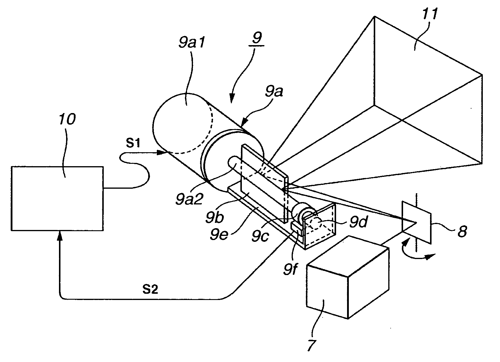
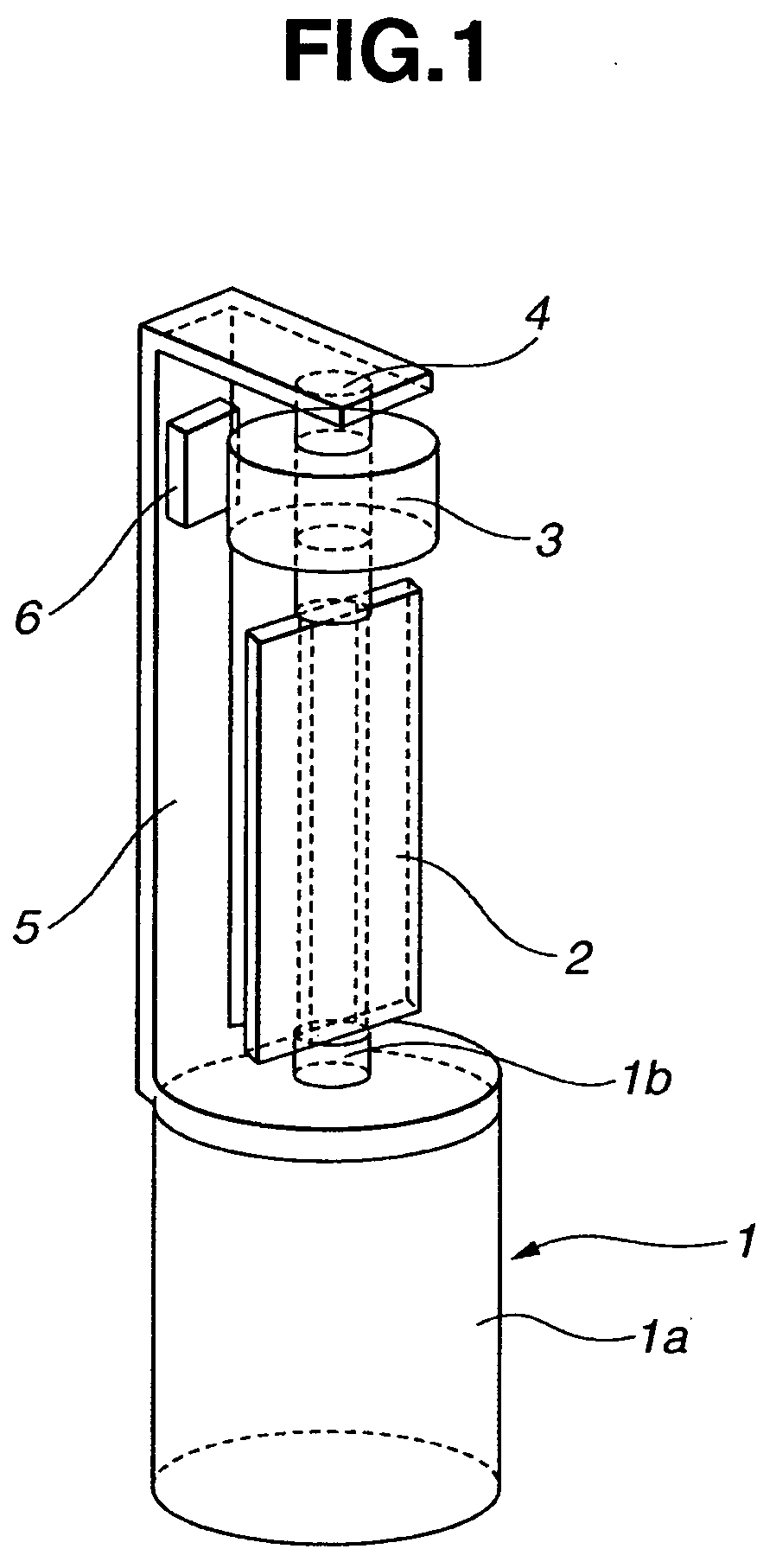
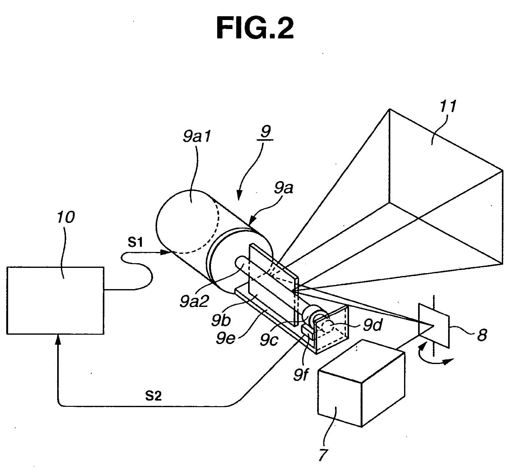
[0017] In an embodiment of a motor apparatus according to the present invention, the motor apparatus includes a motor, such as a step motor, capable of being rotated by electromagnetic force, a load mounted to an output shaft of the motor, and an angular detecting unit for detecting the rotational angle of the output shaft of the motor or the load. In the motor apparatus, the angular detecting unit includes a magnetic sensor, such as a sensor that uses Hall effect, and a magnet, and one of the magnetic sensor and the magnet is fixed to the output shaft of the motor or to a rotational axis portion of the load on a side opposite to a side of the motor with the load interposed therebetween.

[0018] Either the magnetic sensor or the magnet can be fixed to the output shaft of the motor or the rotational axis portion of the load, because it is only required for magnetic field fro...


PUM


Abstract

A motor apparatus has a motor which is rotatable by electromagnetic force, a load mounted to an output shaft of the motor, and an angular detecting unit for detecting a rotational angle of the output shaft of the motor or the load. In the motor apparatus, the angular detecting unit has a magnetic sensor and a magnet, and one of the magnetic sensor and the magnet is fixed to the output shaft of the motor or to the rotational axis portion of the load on a side opposite to a side of the motor with the load interposed therebetween.

Description

BACKGROUND OF THE INVENTION [0001] 1. Field of the Invention [0002] The present invention relates to a motor apparatus, and an optical scanning apparatus using the motor apparatus. [0003] 2. Description of the Related Background Art [0004] With a motor apparatus for driving a drive object by a motor that is rotated or swung with an electromagnetic force, feedback control is typically carried out so that the position, the speed, and other parameters of a drive load (the drive object) can be accurately controlled. In the feedback control, when the position of the drive object is fed back, the feedback is performed in a system from the motor to the drive object, involving characteristics of the backlash of a gear, for example. As a result, the drive object can be controlled with accuracy. However, a detecting unit for detecting the position must cover the entire moving range of the drive object, and the cost of the detecting unit is hence likely to increase. [0005] On the other hand, w...

Claims


Application Information

Patent Timeline
IPC IPC(8): G05B19/40
CPCH02K11/0021G02B26/105H02K11/215
Inventor SOEDA, YASUHIRO
Owner CANON KK
Why Eureka
Eureka Blog
Learn More