Method and apparatus for changing the polarization of a signal

Inactive Publication Date: 2006-03-30
TELEDYNE LICENSING
View PDF8 Cites 10 Cited by
  • Summary
  • Abstract
  • Description
  • Claims
  • Application Information

AI Technical Summary

Benefits of technology

[0008] A method and structure are provided that can be used for bi-directional amplification without duplicative power modules, or for other applications that benefit from controllably varying the polarization of a signal such as an RF switch. A po

Problems solved by technology

One problem associated with the prior art power modules described above is the unidirect

Method used


Image

  • Method and apparatus for changing the polarization of a signal
  • Method and apparatus for changing the polarization of a signal
  • Method and apparatus for changing the polarization of a signal

Examples


Embodiment Construction

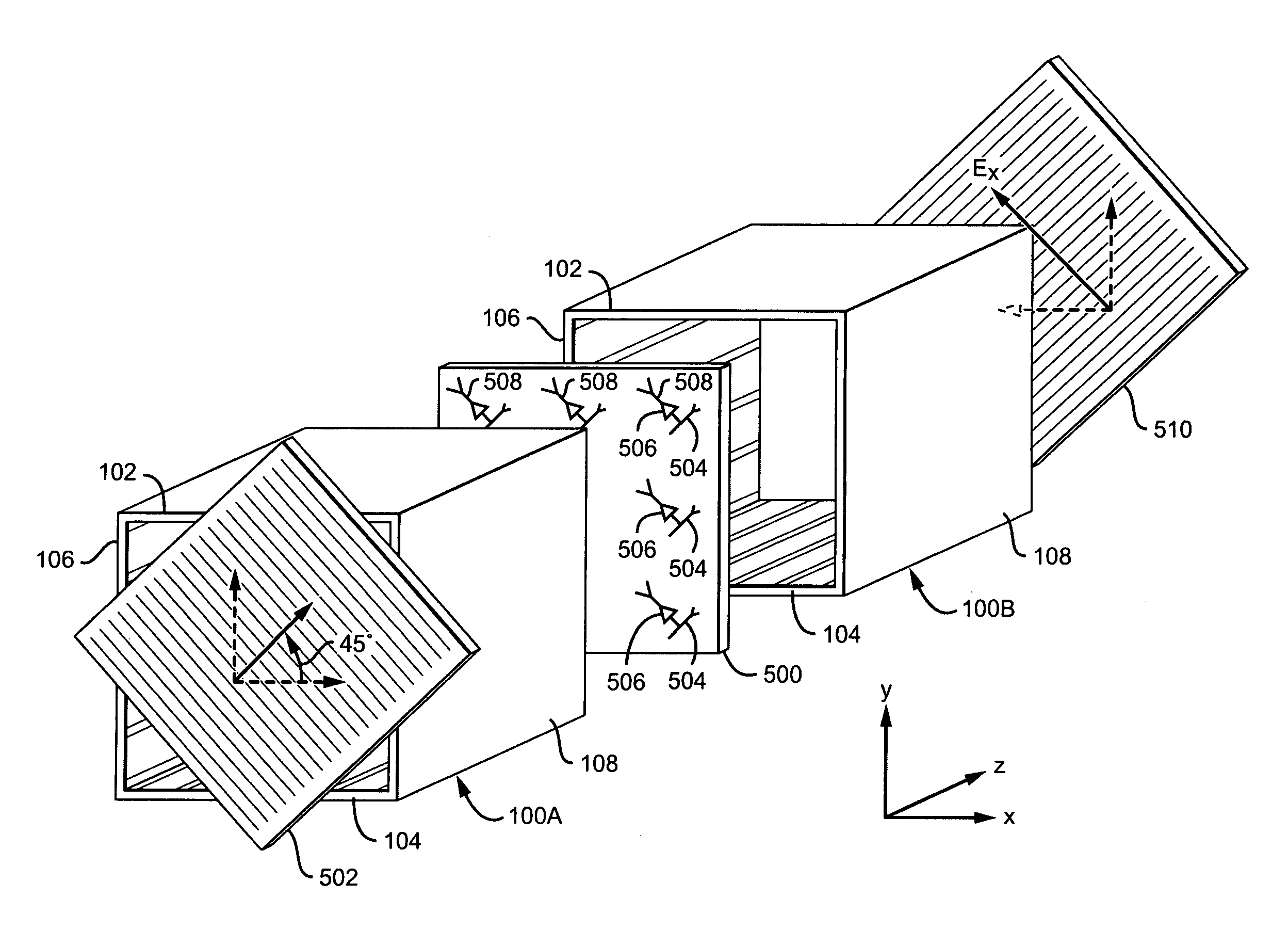
[0021] The invention provides a method and system for changing the polarization of a high-frequency input signal. A linearly polarized signal having an E-field component is propagated a suitable transmission system in which one of the E-field's orthogonal vector components can be phase shifted with respect to the other to change the polarization of the signal. For example, one vector component can be phase shifted relative to the other to change the polarization of a polarized signal from linear to circular and then to linear at a 90 degree angle to the original polarization.

[0022] Several embodiments are described in the context of an impedance-wall waveguide used to match the polarization of an input E field to the input antenna of an amplifier array. Other applications also make use of the changeable polarization, including switching, phase shifting, and signal isolation.

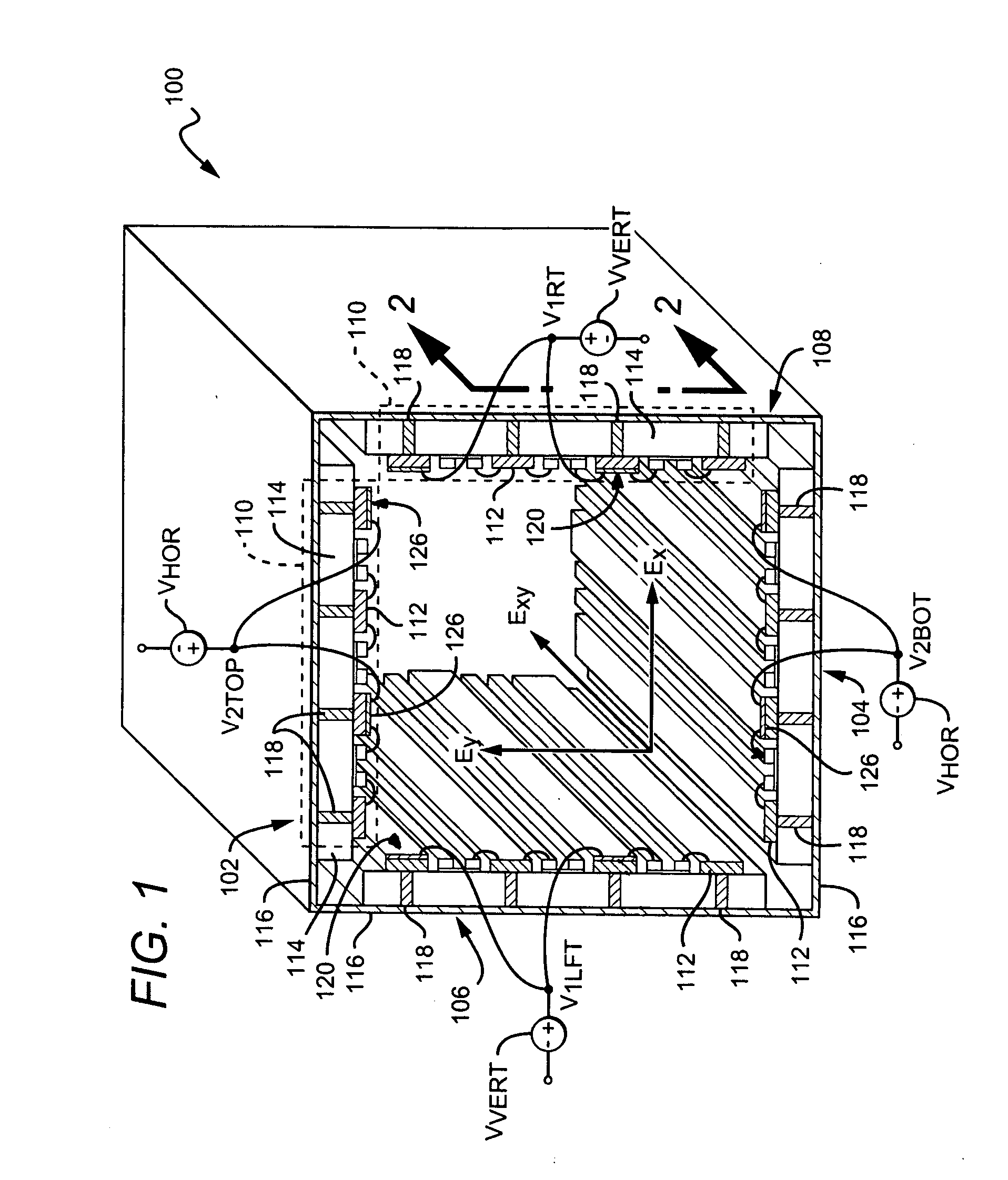
[0023]FIG. 1 illustrates an implementation of an impedance-wall waveguide 100 having interior dimensions equ...


PUM


Abstract

A method and apparatus for changing the polarization of an input signal includes propagating a polarized input signal having orthogonal E-field components by at least one surface each having a respective surface impedance and varying at least one of the surface impedances to shift the phase of one of the components independently from the other so that the polarity of said input signal is changed. Bi-directional propagation is achieved by rotating polarity in one direction but not the other.

Description

RELATED APPLICATION [0001] This is a Utility application based on a Provisional Application Ser. No. 60 / 614,243, filed Sep. 28, 2004.BACKGROUND OF THE INVENTION [0002] 1. Field of the Invention [0003] This invention relates to electronic systems, and more particularly to the transmission of electromagnetic signals. [0004] 2. Description of the Related Art [0005] An electromagnetic wave propagating through space has orthogonal electric (E) and magnetic (H) field components commonly described in Cartesian coordinates. The concept of using an electromagnetic beam for transmitting information is attractive at high frequencies, such as the frequency band of approximately 20-40 GHz. Transmission of the electromagnetic beam to a destination typically involves the use of a signal-guiding element and one or more amplifiers in a power amplifier module. Functions such as switching and bi-directional amplification are used to accomplish the system. [0006] In U.S. Pat. No. 6,756,866, J. Higgins ...

Claims


Application Information

Patent Timeline
IPC IPC(8): H01P1/165
CPCH01P1/165
Inventor HIGGINS, J. AIDEN
Owner TELEDYNE LICENSING
Why Eureka
Try Eureka