Apparatus for driving an LCD display with reduced power consumption

A technology of LCD display and source driver, applied in static indicators, instruments, etc., can solve the problems of large chip area and high power consumption, and achieve the effect of reducing power consumption and area

Inactive Publication Date: 2008-11-19
TRIDENT MICROSYSTEMS (FAR EAST) LTD
View PDF0 Cites 9 Cited by
  • Summary
  • Abstract
  • Description
  • Claims
  • Application Information

AI Technical Summary

Problems solved by technology

[0014] As mentioned above, the main drawbacks of bo...

Method used


Image

  • Apparatus for driving an LCD display with reduced power consumption
  • Apparatus for driving an LCD display with reduced power consumption
  • Apparatus for driving an LCD display with reduced power consumption

Examples


Embodiment Construction

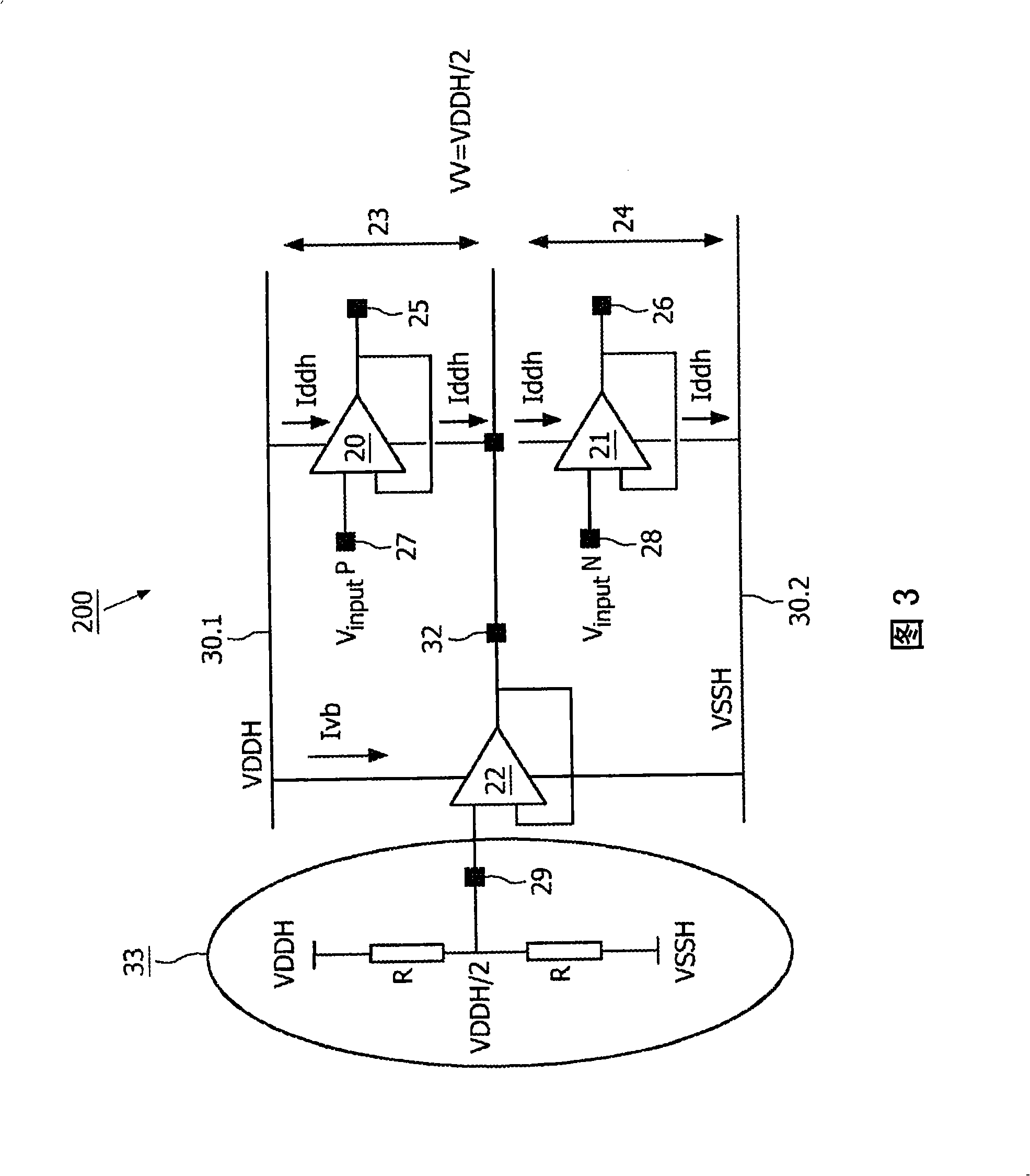
[0035] FIG. 3 shows a first embodiment of the present invention, which shows a part of a source driver 200 for an LCD display. The device includes a power divider 33 , a power buffer 22 , a P rail-to-rail buffer 20 and an N rail-to-rail buffer 21 .

[0036] The power divider 33 consists of two resistors R connected in series between the supply rails VDDH 30.1 and VSSH 30.2, the intermediate node 29 is connected to the input of the power buffer 22.

[0037] The power buffer 22 is arranged between the supply rails VDDH 30.1 and VSSH 30.2, one of its inputs is connected to the intermediate node 29 of the power splitter 33 and to the output 32 . This setup is referred to herein as a voltage follower or unity gain configuration. The power buffer 22 provides at its output 32 a virtual voltage VV approximately half the voltage provided between the two supply rails VDDH and VSSH.

[0038] P rail-to-rail buffer 20 is located between the first power supply rail VDDH and the virtual vo...


PUM


Abstract

Apparatus (200) for driving an LCD display. The apparatus (200) comprises a source driver which is operated between a first power supply rail (VDDH) and a second power supply rail (VSSH). The source driver comprises a power buffer (22) being arranged between the first and the second power supply rails (VDDH, VSSH). The power buffer (22) provides at an output (32) a virtual voltage (VV) of about half the voltage between the two power supply rails (VDDH, VSSH). Furthermore, a P-buffer (20) and an N-buffer (21) are provided. The P-buffer (20) is situated between the first power supply rail (VDDH) and the virtual voltage (VV), and the N-buffer (21) is situated between the virtual voltage (VV) and the second power supply rail (VSSH). The P-buffer (20; 31) is driven at its input side (27) by gamma voltages in an upper voltage regime (VinputP) and the N-buffer (21) is at its input side (28) driven by gamma voltages in a lower voltage regime.

Description

technical field [0001] The invention relates to a device for driving an LCD display. Background technique [0002] The driving circuit of LCD (such as active matrix LCD) can be divided into two parts: source and gate driver. The gate driver controls the gates of the transistors to select and deselect a particular row of pixels. The source drivers provide the desired voltage levels corresponding to the desired intensities of each color to all subpixels of the currently selected row. To this end, source drivers typically include analog output buffers. [0003] LCD driver circuits include more and more channels in a single chip, while output voltage ranges and corresponding analog supply voltages get larger in order to provide increased dynamic range and color depth. Due to the large number of channels and increased supply voltage, one of the most important parameters of the driver circuit, the overall power consumption, is mainly determined by the power consumption of the a...

Claims


Application Information

Patent Timeline
IPC IPC(8): G09G3/36
CPCG09G2330/021G09G3/3696G09G3/3688
Inventor 米伦·佩内瓦谢尔盖·库兹涅佐夫塞拉芬·N·伊图瓦
Owner TRIDENT MICROSYSTEMS (FAR EAST) LTD
Why Eureka
Try Eureka