Image sensors

a technology of image sensor and sensor, applied in the field of image sensor, can solve the problems of high fixed pattern noise (fpn) and other operational noise levels, loss of detail in these clipped areas, and increased system complexity for calibration purposes

Inactive Publication Date: 2006-03-30
STMICROELECTRONICS LTD
View PDF5 Cites 39 Cited by
  • Summary
  • Abstract
  • Description
  • Claims
  • Application Information

AI Technical Summary

Benefits of technology

[0017] According to a second aspect of the invention, there is provided an image sensor comprising a pixel array and control circuitry adapted to carry out the method of the first aspect.
[0018] From a third aspect, a CMOS image sensor according to the second aspect is provided. Fro

Problems solved by technology

Detail in these clipped areas is lost.
However, they suffer from high fixed pattern noise (FPN) and other operational noise levels and increased system complexity for calibration purposes.
However,

Method used


Image

  • Image sensors
  • Image sensors
  • Image sensors

Examples


Embodiment Construction

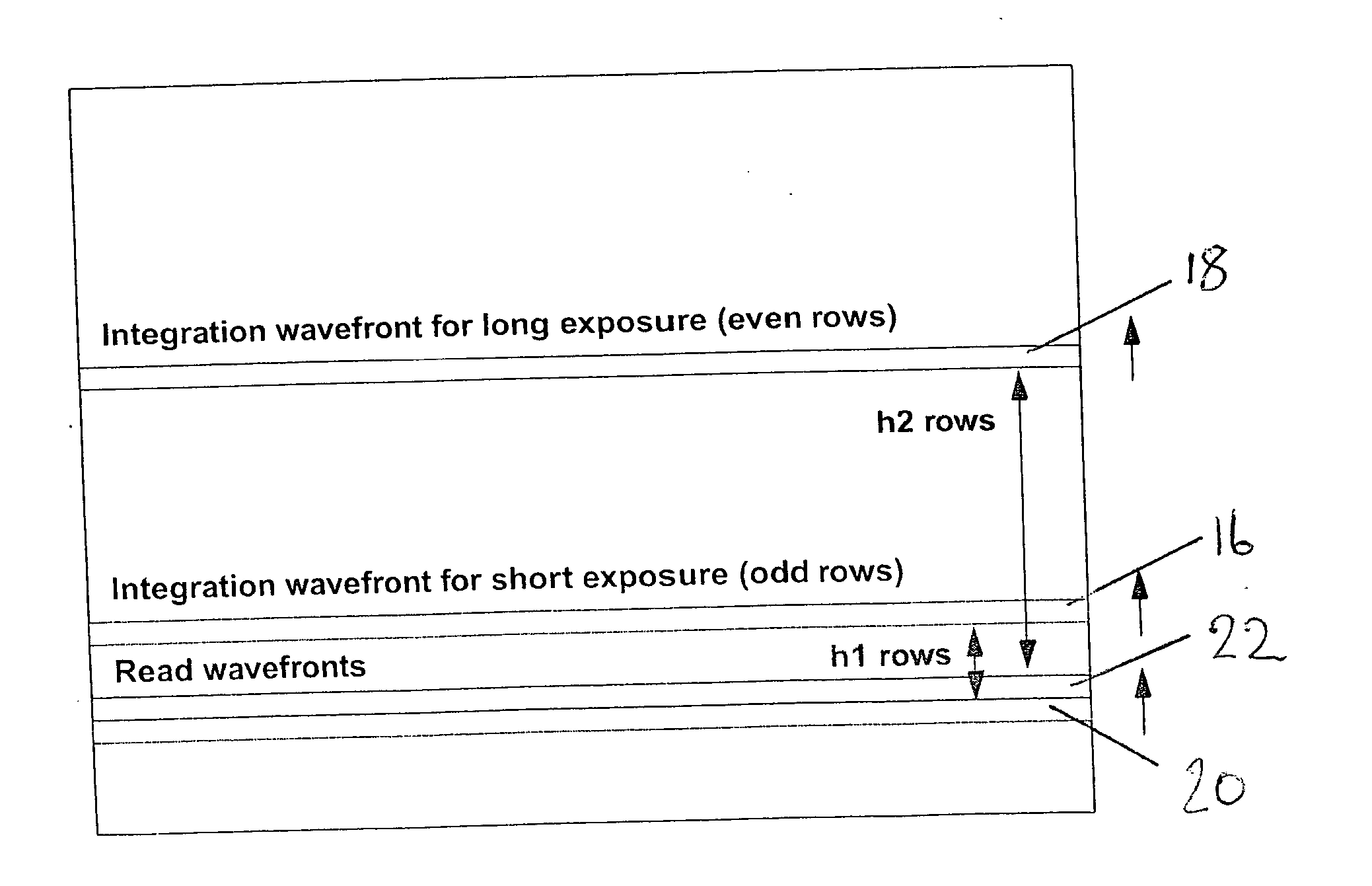
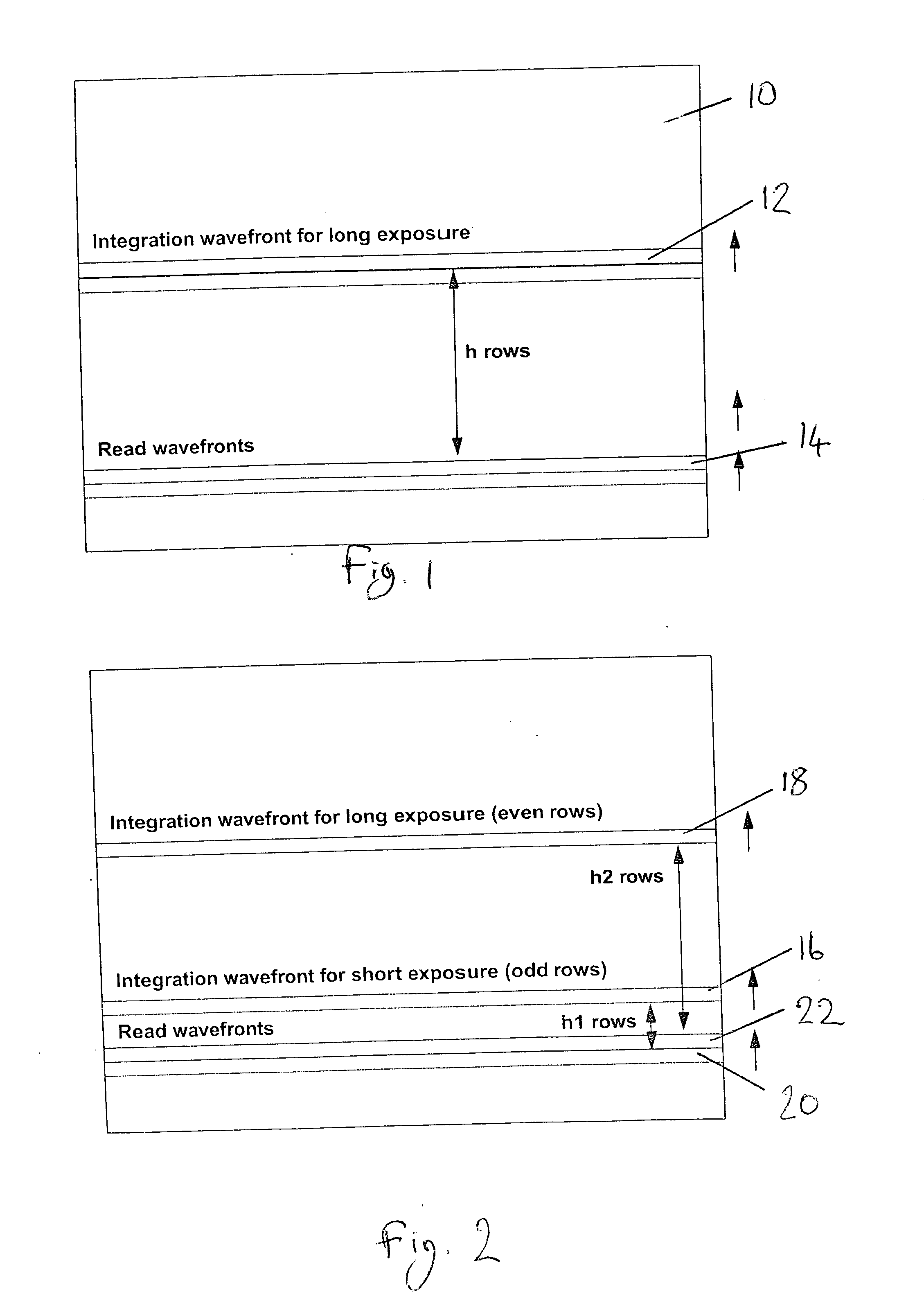
[0024] The scheme shown in FIG. 2 is a means of obtaining extended dynamic range from an image at the expense of lower spatial resolution. A first integration wavefront 16 and a second integration wavefront 18 operate in a rolling blade fashion. Odd lines of the image have a first exposure h1, i.e. there are h1 rows between the first integration wavefront 16 and its corresponding read wavefront 20 and even lines have a second exposure h2, i.e. there are h2 rows between the second integration wavefront 18 and its corresponding read wavefront 22. One exposure (here, h1) is shorter than the other. The ratio between the long and short exposure can be fixed, i.e. h2=kh1.

[0025] This illustrated embodiment can also make use of the concept of fine exposure, whereby the short exposure h1 can be adjusted as a fraction of a line time rather than in integer multiples. Thus the integration wavefront occurs within the previous line being read out. The integration point can be adjusted by single ...


PUM


Abstract

A rolling blade exposure system includes odd rows of a pixel array being read out with a short exposure time and even rows being read out at a long exposure time. Each pair of sampled rows are stitched together before to form a single output line. The resultant image is then formed from the output lines. The stitching process ensures that the resultant image has a wide dynamic range. This is achieved at the expense of a loss of resolution, but this loss is acceptable for certain applications.

Description

FIELD OF THE INVENTION [0001] The present invention relates to image sensors, and in particular, to rolling blade exposure techniques to extend dynamic range in CMOS image sensors. BACKGROUND OF THE INVENTION [0002] A solid state image sensor, such as a CMOS image sensor, comprises an array of pixels. Light is incident on these pixels for an integration time, and the resulting charge is converted to a voltage before being read out. The readout process includes converting the analogue voltage to a digital value and then processing the collected digital values to construct an image. As pixel arrays comprise a large number of pixels, it is common to read out selected subsets of pixels, for example, a row, at a time. [0003]FIG. 1 shows a typical “rolling blade” exposure system implemented in a CMOS image sensor. A pixel array 10 comprises a number of rows of pixels. A first row of pixels is put into integration at time t(n−h) and is read out at time t(n) where h is a number of lines of ...

Claims


Application Information

Patent Timeline
IPC IPC(8): H04N5/235
CPCH04N3/155H04N5/23245H04N5/35581H04N5/3452H04N5/3532H04N5/343H04N23/667H04N25/441H04N25/42H04N25/531H04N25/589
Inventor HENDERSON, ROBERTPURCELL, MATTHEWSTORM, GRAEME
Owner STMICROELECTRONICS LTD
Why Eureka
Try Eureka