Printing system

a printing system and printing technology, applied in the field of printing systems, can solve the problems of insufficient power of the fuser to handle high thermal mass materials without experiencing, difficulty in printing on media of varying substrate weight, surface roughness and coating weight, etc., and achieve the effect of reducing the overall efficiency and throughput rate of the machin

a printing system and printing technology, applied in the field of printing systems, can solve the problems of insufficient power of the fuser to handle high thermal mass materials without experiencing, difficulty in printing on media of varying substrate weight, surface roughness and coating weight, etc., and achieve the effect of reducing the overall efficiency and throughput rate of the machin

US20060066885A1Inactive Publication Date: 2006-03-30XEROX CORP

Image

  • Printing system
  • Printing system
  • Printing system

Examples


Embodiment Construction

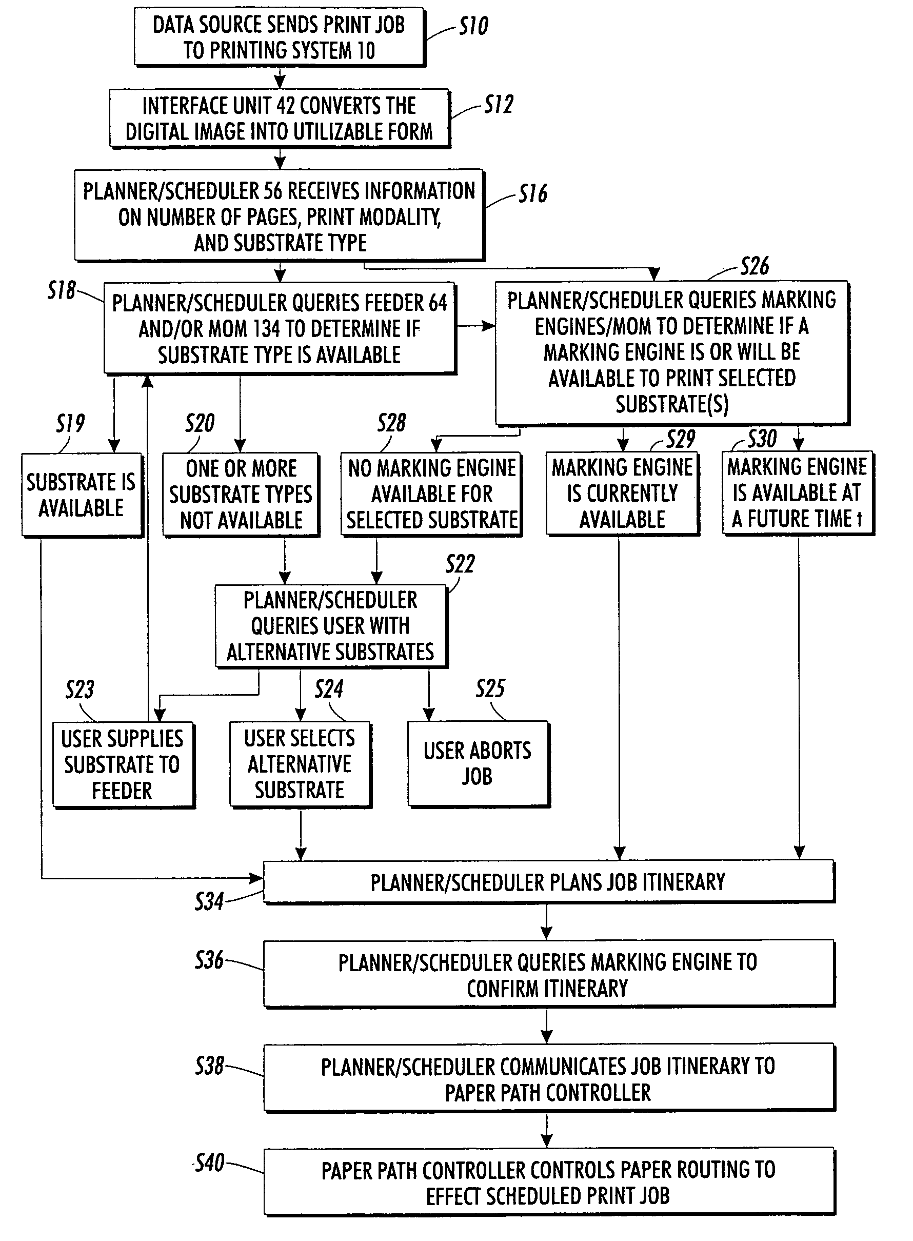
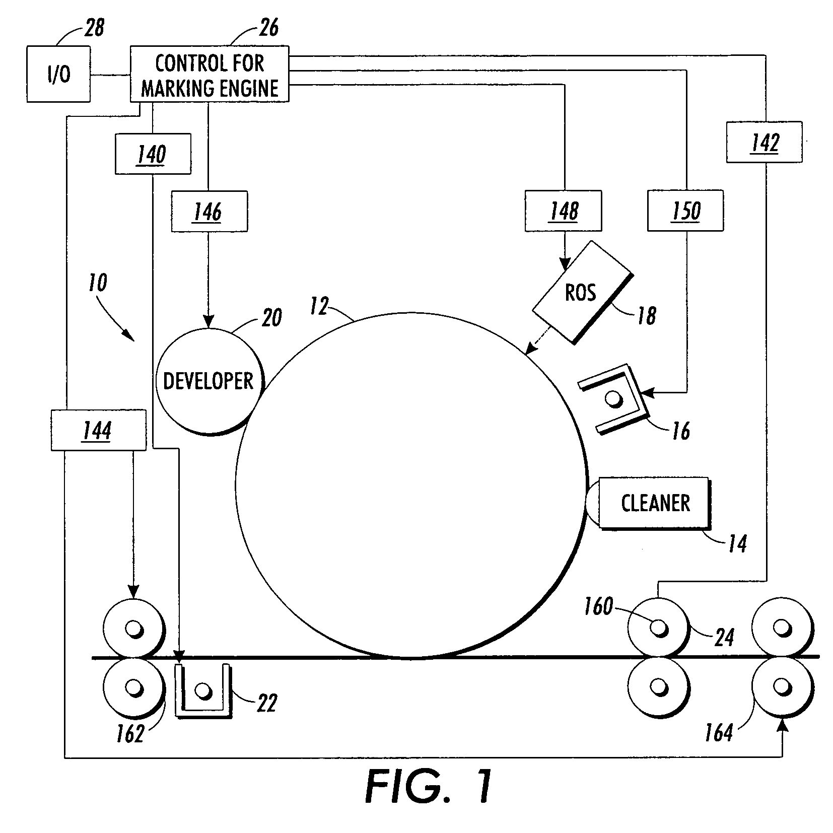
[0030] Aspects of the present exemplary embodiment relate to a printing system and method for printing off-normal print media as well as normal print media. The system allows modification of the xerographic subsystems of one or more marking engines to modify throughput rate and / or other marking engine parameters through scheduling algorithms which comprehend subsystem temporal latitude limits when running off-normal media.

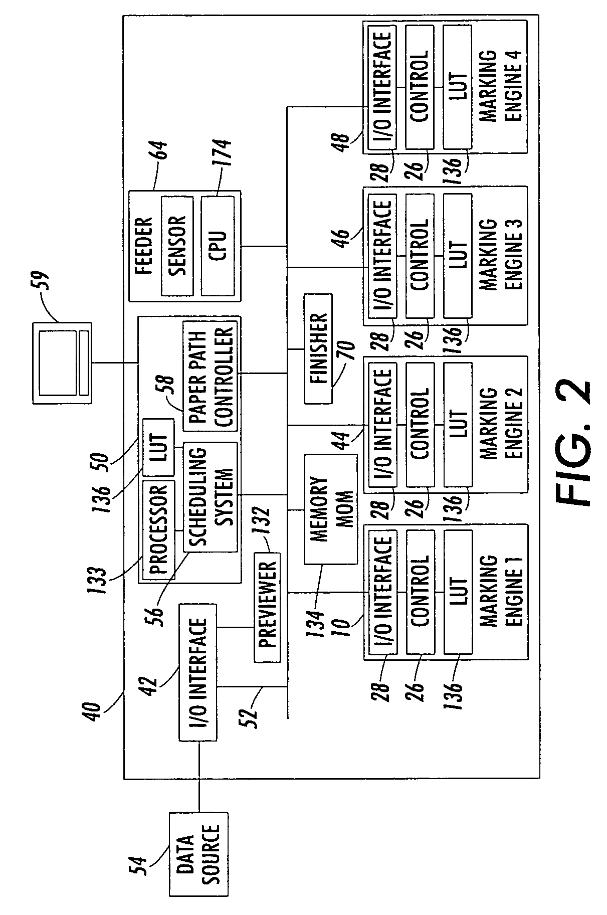
[0031] The printing method may include processing a print job stream to identify at those images which are to be printed on a first substrate, such as an off-normal substrate having a substrate attribute which is different from a second substrate, such as a normal substrate. One or more of at least two marking engines in the printing system which are configured for printing images of a common print job stream is selected to print the identified images on the off-normal first substrate. An operating parameter of the selected marking engine(s) is modified from a set...


PUM


Abstract

A method of printing includes processing a print job stream to identify one or more images to be printed on a first substrate. The first substrate has a substrate attribute, such as paper weight or surface roughness, which is different from that of a second substrate. A marking engine is selected to print the identified images on the selected first substrate. An operating parameter of the marking engine is modified from a set point for the second substrate to a modified set point for the first substrate, to accommodate the substrate attribute of the selected first substrate. The identified images are sent to the selected marking engine to be printed.

Description

CROSS-REFERENCE TO RELATED APPLICATIONS [0001] This application claims the benefit, as a Continuation-in-Part, of U.S. application Ser. No. 10 / 953,953, filed Sep. 29, 2004, entitled “CUSTOMIZED SET POINT CONTROL FOR OUTPUT STABILITY” (as amended), by Charles A. Radulski, et al., the disclosure of which is totally incorporated herein by reference. [0002] The following applications, the disclosures of each being totally incorporated herein by reference are also mentioned: [0003] U.S. Provisional Application Ser. No. 60 / 631,651 (Attorney Docket No. 20031830-US-PSP), filed Nov. 30, 2004, entitled “TIGHTLY INTEGRATED PARALLEL PRINTING ARCHITECTURE MAKING USE OF COMBINED COLOR AND MONOCHROME ENGINES,” by David G. Anderson, et al.; [0004] U.S. application Ser. No. 10 / 917,768 (Attorney Docket 20040184-US-NP), filed Aug. 13, 2004, entitled “PARALLEL PRINTING ARCHITECTURE CONSISTING OF CONTAINERIZED IMAGE MARKING ENGINES AND MEDIA FEEDER MODULES,” by Robert M. Lofthus, et al.; [0005] U.S. app...

Claims


Application Information

Patent Timeline
30 Mar 2006
Publication
US20060066885A1
IPC
G06F3/12
CPC
G03G15/50; H04N1/2307; H04N1/2323; H04N1/2392; H04N1/2346; H04N1/2353; H04N1/2361; H04N1/2338
Inventors
ANDERSON, DAVID G.; RADULSKI, CHARLES ANTHONY