Disk drive device with temperature and humidity control

a technology of temperature and humidity control and disk drive, which is applied in the direction of magnetic recording, record carrier contruction details, magnetic disk recording, etc., can solve the problems of moisture condensation on the head and the disk, the relative humidity of the entire air rises, and the temperature change influence is reduced, so as to achieve excellent reliability

Inactive Publication Date: 2006-03-30
HITACHI GLOBAL STORAGE TECH NETHERLANDS BV
View PDF7 Cites 91 Cited by
  • Summary
  • Abstract
  • Description
  • Claims
  • Application Information

AI Technical Summary

Benefits of technology

[0023] According to the invention, it is possible to provide a disk drive device excell...

Problems solved by technology

In a disk drive device mounted on a portable apparatus and an information apparatus for vehicles, in particular, problems occur when moisture condensation is caused on a head and a disk following a rapid fall in temperature outside a housing and when a disk surface dries following a rapid rise in ambient temperature.
Consequently, whereas a rise in relative humidity of the entire air in the housing delays considerably, a rapid rise in relative humidity occurs on surfaces of the head and the disk.
As a result, moisture condensation occurs on the head and the disk.
As a result, the disk surface...

Method used


Image

  • Disk drive device with temperature and humidity control
  • Disk drive device with temperature and humidity control
  • Disk drive device with temperature and humidity control

Examples


first embodiment

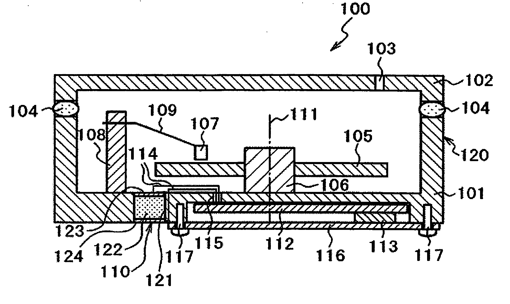
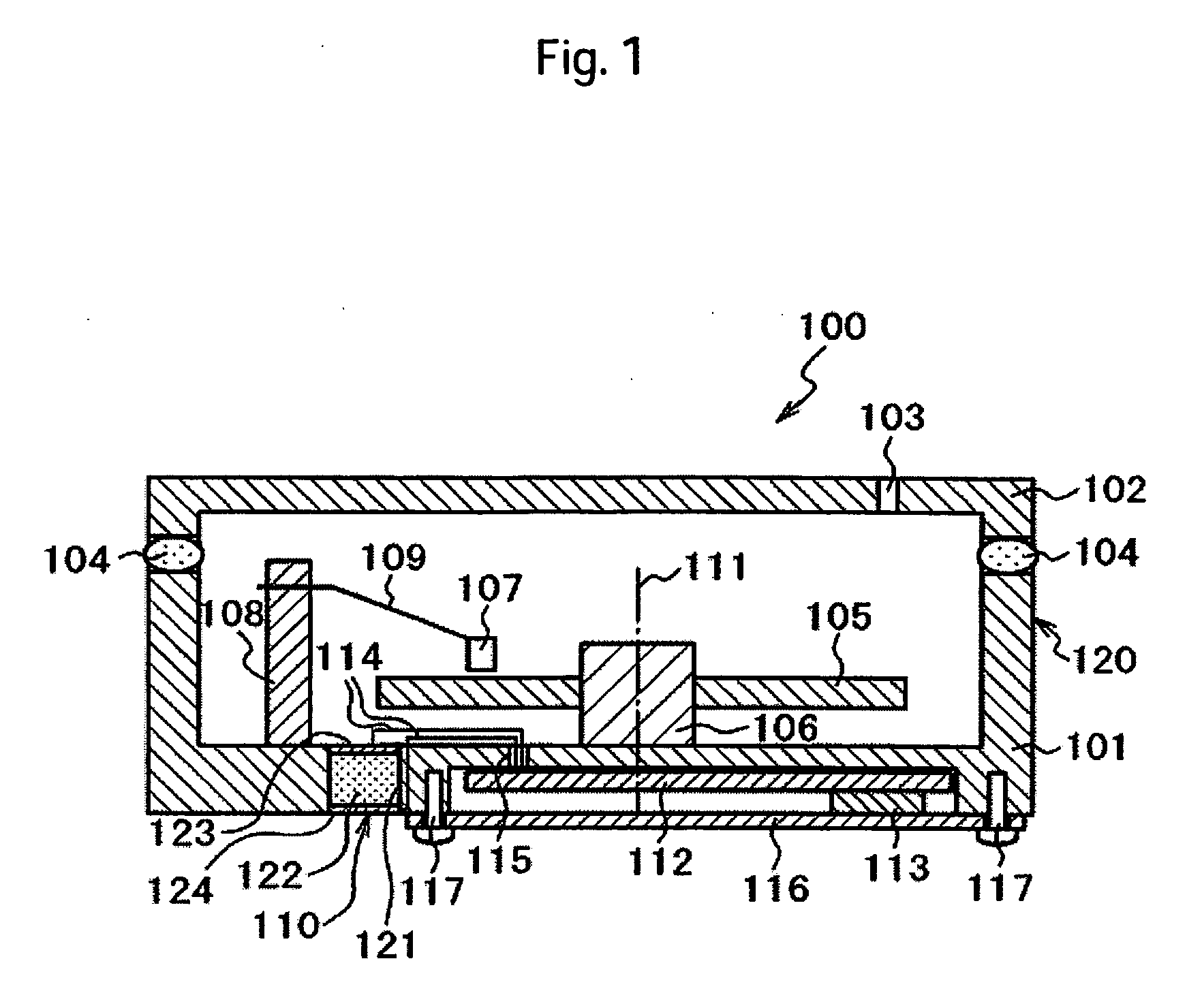
[0033] An overall structure of the disk drive device in the embodiments will be explained with reference to FIG. 1. FIG. 1 is a diagram of a disk drive device 100 in the invention cut along a disk rotation axis 111. Note that the disk drive device 100 in this embodiment is an example of a magnetic disk drive device.

[0034] The disk drive device 100 includes a disk 105, a spindle motor 106, a head 107, a head drive mechanism 108, a suspension arm 109, a humidity control element 110, a circuit board 112, a temperature sensor 113, and a housing 120 as main components.

[0035] The housing 120 includes a base 101 and a cover 102 and is formed in a box shape having a closed inner space. A fine breathing hole 103, which communicatively connects the inner space of the housing 120 and an outer space, is formed in the cover 102. The base 101 and the cover 102 are made of a metal material such as aluminum. A sealing member 104 is provided between the base 101 and the cover 102. A disk drive mech...

second embodiment

[0063] In the second embodiment, as shown in FIG. 6, a humidity sensor 118 for detecting humidity in a housing is set on a surface of the base 101. The wiring 114 lead out from the humidity sensor 118 are connected to the circuit board 112 through the through hole 115.

[0064] An operation of the control circuit in the second embodiment will be explained with reference to FIG. 7. As in the first embodiment, the control circuit detects the start of power supply to the disk drive device 100 and a starting operation of the device (S201) and checks the presence or absence of a stop instruction for the disk drive (S202). If there is no stop instruction, the control circuit starts control of the humidity control element 110.

[0065] In the control of the humidity control element 110, first, the control circuit detects an output T of the temperature sensor 113 mounted on the circuit substrate 112 and compares the output T with an upper limit value and a lower limit value set in advance (S203)...

third embodiment

[0073] In the third embodiment, the temperature sensor 113 is arranged to be in abutment against the base 101. Consequently, it is possible to detect ambient temperature even when the cover 116 is made of a material with a low thermal conductivity. In addition, it is possible to detect ambient temperature promptly because the base 101 with a lower thermal resistance is used as a heat conduction path.

[0074] Note that an installation location of the temperature sensor is not limited to the location described in the first embodiment or the third embodiment. Certain functions of the invention are attained as long as the installation location is in a mounting position where temperature changes following a temperature change outside the disk drive device. It is possible to detect temperature substantially the same as ambient temperature by mounting the temperature sensor 113 on, for example, the side wall of the base 101 and surfaces of the cover 102, the spindle motor 106 heat-conductive...


PUM


Abstract

Embodiments of the invention provide a disk drive device excellent in reliability that can reduce influence of a temperature change in an environment of use. In one embodiment, a disk drive device includes a disk drive mechanism that records information in a disk or reproduces information stored in the disk and a housing in which the disk drive mechanism is housed. The disk drive device further includes a humidity control element that controls humidity in the inside of the housing, a temperature sensor that detects ambient temperature of the disk drive device or temperature of a portion where temperature changes substantially in the same manner as the ambient temperature, and a control circuit that controls the temperature control element on the basis of a rapid change in temperature detected by the temperature sensor.

Description

CROSS-REFERENCES TO RELATED APPLICATIONS [0001] This application claims priority from Japanese Patent Application No. JP2004-276568, filed Sep. 24, 2004, the entire disclosure of which is incorporated herein by reference. BACKGROUND OF THE INVENTION [0002] The present invention relates to a disk drive device and is, in particular, suitable for a disk drive device that is mounted on a portable apparatus and an information apparatus for vehicles. [0003] In environments of use of portable apparatuses and information apparatuses for vehicles, in general, temperature and humidity change in a wide range compared with those used in offices, computer rooms, and the like and often involve rapid changes. In disk drive devices exposed to such environments, temperature in a housing, in which a disk is housed, changes rapidly and significantly to affect reliability of the apparatuses significantly. In a high-humidity environment, a head and a disk may attract each other to be damaged because of ...

Claims


Application Information

Patent Timeline
IPC IPC(8): G11B19/02G11B33/14
CPCG11B33/1406G11B33/14
Inventor AKAMATSU, NAOTOSHIFUJITA, YUJI
Owner HITACHI GLOBAL STORAGE TECH NETHERLANDS BV
Why Eureka
Try Eureka