
Lead acid battery with gelled electrolyte contained within compressed absorbent separator mat and method of making the same

a technology of gelled electrolyte and separator mat, which is applied in the direction of non-aqueous electrolyte cells, cell components, sustainable manufacturing/processing, etc., can solve the problems of battery maintenance that requires water addition, battery overcharge, and loss of contact with electrodes

Inactive Publication Date: 2006-03-30
C&D CHARTER HLDG
View PDF7 Cites 38 Cited by
  • Summary
  • Abstract
  • Description
  • Claims
  • Application Information

AI Technical Summary

Problems solved by technology

These reactions are reversed during charge, but a significant amount of secondary reactions also occur, thus requiring overcharge.
In flooded (or vented) battery designs the oxygen and other gasses escape from the battery resulting in battery maintenance that requires the addition of water.
Over time, however, the gel tends to dry out and shrink thereby losing contact with the electrode and adversely affecting performance.
This is especially true in motive power applications where voltages and temperatures are not tightly controlled.
The porous mat, however, often loses compression over time thereby adversely affecting the battery performance.
Such peripheral sealing, however, did not address the concerns of maintaining porous mat and electrode contact over time.
While these patents or publications describe advantages for the use of gelled electrolyte in free spaces between battery electrodes, such gelled filled free spaces increase the overall dimensions of the battery case as compared to batteries not having such free spaces and do not fully address the concern of gel dry out.
In addition, they do not address the need for maintaining a compressive force while fully immobilizing the electrolyte.
Such a gelled electrolyte would not be useful in a VRLA battery because the lack of cracks or fissures would prohibit oxygen transfer and thereby prevent or limit oxygen recombination.
The use of porous mat that are preformed with solid gel-forming agents, however, is expensive and sometimes cumbersome as care must be taken to avoid loss or maldistribution of the powdered gelling agent in the porous mat.
Presence of the siliceous materials stiffens the mat and thereby creates difficulties for battery assembly and for establishing the necessary compressive force between the electrode plates.

Method used


Image

  • Lead acid battery with gelled electrolyte contained within compressed absorbent separator mat and method of making the same
  • Lead acid battery with gelled electrolyte contained within compressed absorbent separator mat and method of making the same
  • Lead acid battery with gelled electrolyte contained within compressed absorbent separator mat and method of making the same

Examples


example 1

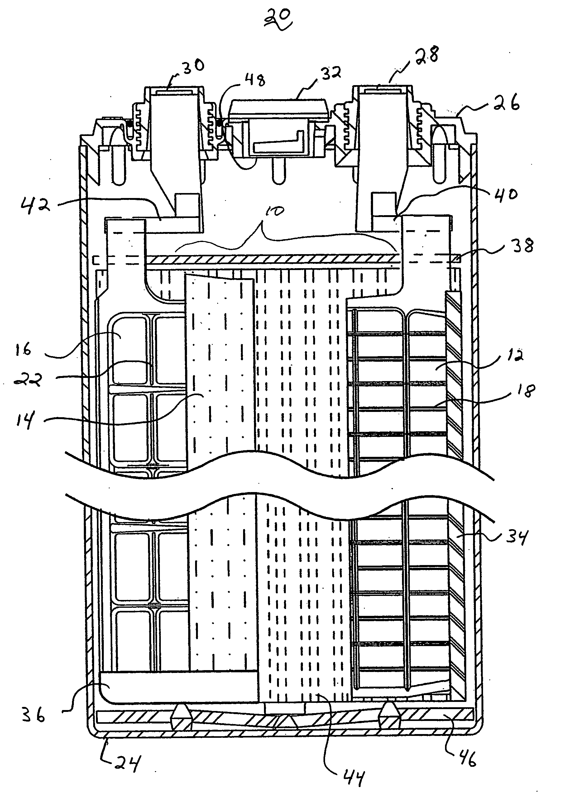
[0068] Cells shown in FIG. 6 consisted of two different groups of cells. Control cells 1 and 2 both consisted of cells manufactured with tank formed plates that were dry charged, filled with only acid and activated (charged), then cycled in the vertical position. Control cells I and 2 had the porous mats filled with acid and not with the electrolyte contained in the inventive cells. The inventive cells 1 and 2 had mats filled with a gelled electrolyte according to the present invention. Both the control and inventive cells were cycled in vertical orientation rather than lying down. End of discharge voltages for both groups of cells were measured. Control cells 1 and 2 declined in discharge voltages from about 100 to about 200 cycles. The inventive cells had superior performance as exhibiting no decline in end of discharge voltage over the same number of cycles and only had noticeably decline in end of discharge voltage after about 700 to about 900 cycles.

[0069] In order to determin...

example 2

[0071] Cells were formed with the plates and mats of example 1. FIG. 7 shows the performance for two different types of sealed motive, 6 cell batteries. The control battery consists of jar formed positive and negative electrodes with glass mat separators filled only with electrolyte and not with the electrolyte and colloidal polysilica mixture. The second battery consists of inventive cells. Both batteries were cycled in the vertical orientation. The inventive cells show far superior performance while the control cells decline in capacity in less than 100 cycles, primarily due to severe electrolyte stratification.


PUM

PropertyMeasurementUnit
uncompressed porosityaaaaaaaaaa
compressed porosityaaaaaaaaaa
particle sizeaaaaaaaaaa

Abstract

A method for producing a valve-regulated lead acid battery includes the steps of (i) providing a battery comprising a preformed positive electrode plate, a preformed negative electrode plate and a porous separator mat having pores and being compressibly disposed between the electrodes to define a cell assembly, and a container for securably and sealingly holding the cell assembly; (ii) forming a electrolyte mixture comprising an aqueous colloidal dispersion of silica and sulfuric acid that is a precursor to a flowable thixotropic gel; (iii) applying a vacuum to the container; and (iv) introducing a quantity of the gel-precursor electrolyte into the container under a vacuum so that the flowable electrolyte mixture penetrates into the pores of the compressed mat, whereby as the acid absorbs onto the plates, the flowable electrolyte solidifies and forms a thixotropic gel within the pores and around peripheral edges of the mat to surround and seal the cell assembly. A battery produced by these steps include (i) a positive electrode plate; (ii) a negative electrode plate; (iii) an absorbent glass mat compressibly disposed between the electrodes, wherein the glass mat is in substantial contact with both electrodes; and (iv) gelled electrolyte disposed within the pores of the compressed glass mat and around peripheral edges of the glass mat, wherein the gelled electrolyte comprises of an intimate mixture of colloidal alkali metal polysilica having a particle size from about 4 nanometers to about 20 nanometers and sulfuric acid.

Description

FIELD OF THE INVENTION [0001] The present invention is directed to a lead acid battery that is a hybrid of gelled electrolyte lead acid battery and an absorbent porous mat lead acid battery. More particularly, the present invention is a valve-regulated lead acid battery having gelled electrolyte contained within the pores of porous glass separator mat, which are compressibly disposed between positive and negative electrode-plates. BACKGROUND OF THE INVENTION [0002] A lead-acid battery is comprised of one or more each of positive and negative plates that are spaced apart and inter-leafed with a separator between each plate pair, together with an electrolyte constituted from diluted sulfuric acid. When a lead-acid battery is discharged, sponge lead (Pb) at the negative plate and lead dioxide (PbO2) resident at the positive plate are converted into lead sulfate (PbSO4). Thus, during discharge the sulfate of the sulfuric acid is absorbed into the electrodes. These reactions are reversed...

Claims


Application Information

Patent Timeline
Patent Type & Authority Applications(United States)
IPC IPC(8): H01M10/10H01M10/04H01M2/16H01M50/437H01M50/491
CPCH01M2/1613H01M10/10Y10T29/49115H01M2300/0085Y02E60/126H01M10/12Y02E60/10H01M50/44Y02P70/50H01M50/437H01M50/491
Inventor MRAZ, STEPHEN L.DILLON, JAMES D. IIIMISRA, SUDHAN S.NOVESKE, TERRENCE M.
Owner C&D CHARTER HLDG
Learn More