Method and system for dynamic range power control

Inactive Publication Date: 2006-03-30
MOTOROLA INC
View PDF8 Cites 10 Cited by
  • Summary
  • Abstract
  • Description
  • Claims
  • Application Information

AI Technical Summary

Benefits of technology

[0005] In a first embodiment of the present invention, a system for current efficient dynamic power range control in a transmitter lineup can include a switched mixer coupled to a switched step attenuator and a switched power driver coupled to the switched step attenuator. In such a system, linearity and efficiency can be substantially maintained for more than 70 dB of dynamic power range for the system. The dynamic power range control can all occur within the radio frequency range and current can be dynamically switched along with the output power. In one particular embodiment, the transmitter allows for over 30 dB of continuous power control and over 45 dB of discrete power control at a predetermined number of dB steps. The switched mixer and the switched step attenuator can be FET based and the system can be fully integrated in CMOS circuitry or bipolar circuitry. The switched power driver can further include continuous power control via current steering and more specifically the switched power driver can be a combination stacked current steer and a current switched IQ summer amplifier where the current switched IQ summer amplifier can provide over 60 dB power control range. The switched power driver can also include a parallel gain driver providing relatively wide bandwidth.
[0006] In a second embodiment of the present invention, a system of current efficient dynamic power range control in a transmitter lineup can include means for providing over 70 dB of power control range in the transmitter lineup, means for maintaining substantial signal linearity and current efficiency throughout a complete power control range, and means for minimizing distortion by distributing distortion effects over a plurality of components in the transmit

Problems solved by technology

The ability to have over 70 dB of power control range in an Radio Frequency (RF) lineup in practicality is very difficult due to isolation requirements, the amount of current required and linearity requirements.
To obtain the required power control range and the appropriate isolation usually means the use of several stages in a lineup each consuming current or contributing to path loss and creating noise and non-linearities.
Furthermore, maintaining a required or substantial signal linearity at all attenuation settings in a current efficient manner is also quite difficult for such a wide power control range.
Existing systems fail to provi

Method used


Image

  • Method and system for dynamic range power control
  • Method and system for dynamic range power control
  • Method and system for dynamic range power control

Examples


Example

DETAILED DESCRIPTION OF THE DRAWINGS

[0013] While the specification concludes with claims defining the features of embodiments of the invention that are regarded as novel, it is believed that the invention will be better understood from a consideration of the following description in conjunction with the figures, in which like reference numerals are carried forward.

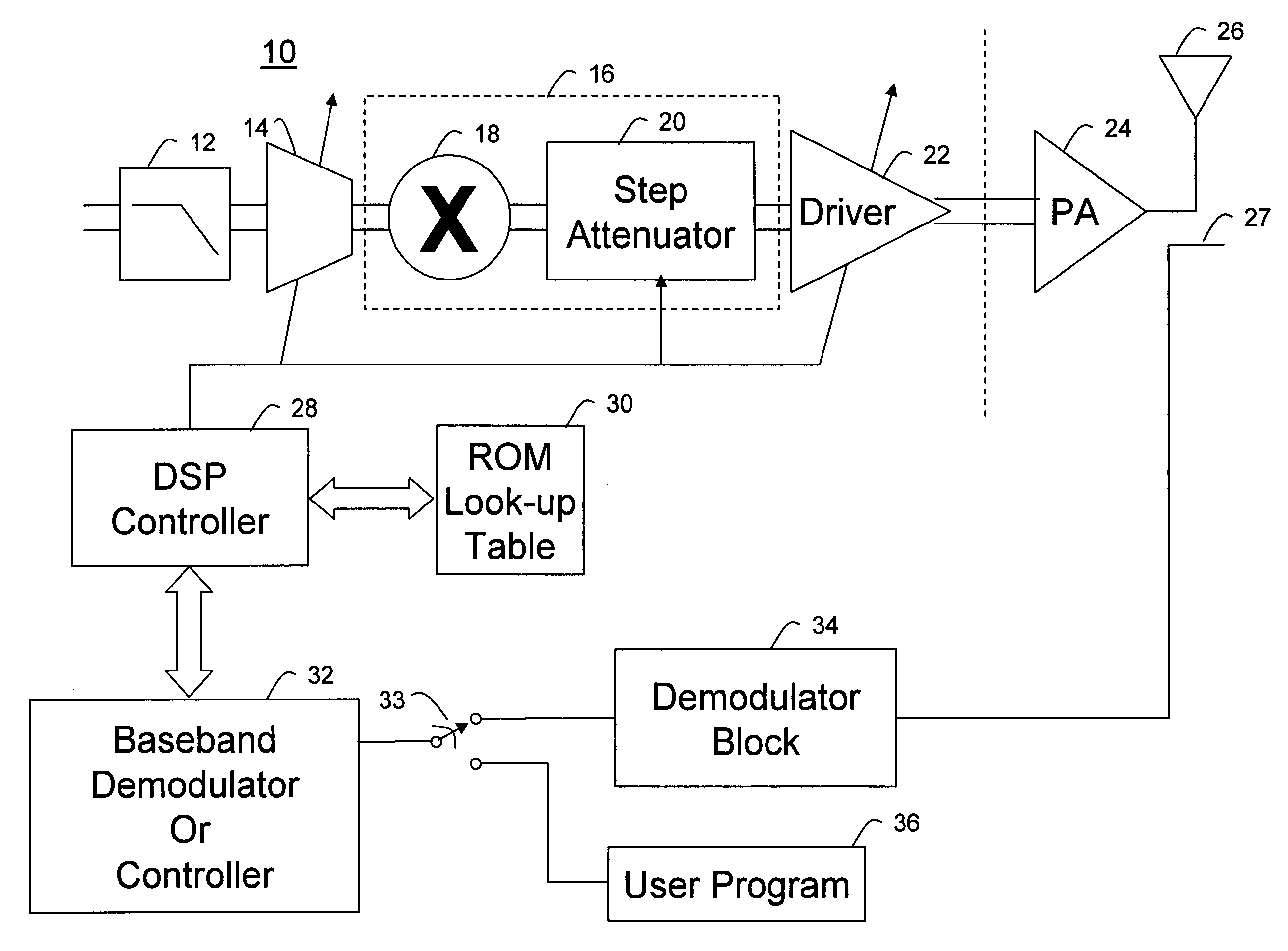
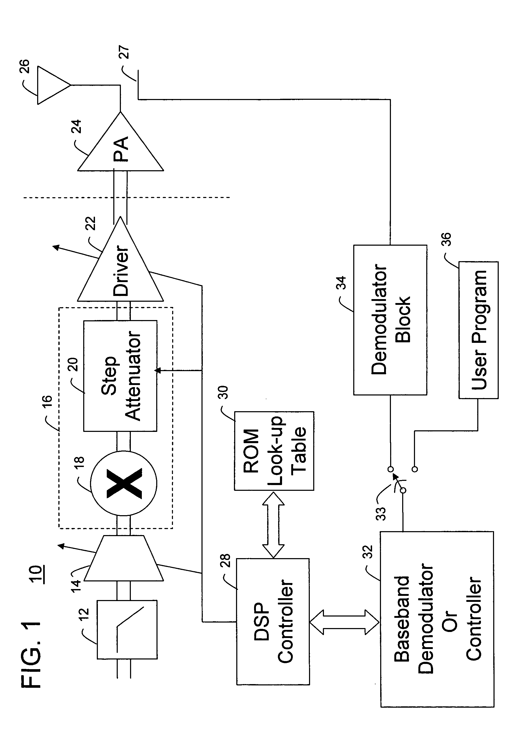
[0014] Referring to FIG. 1, a transmitter lineup 10 having at least 70 dB of power control range is shown. The transmitter lineup 10 can be fully integrated in an all CMOS embodiment or alternatively bipolar technology. The transmitter lineup 10 can include a baseband filter 12 receiving a baseband input and a current controlled baseband driver 14. The power control primarily occurs in two portions of the transmitter lineup, namely a voltage divider portion or circuit 16 and a current controlled output driver 22. The voltage divider circuit 16 is wide bandwidth since no resistors are used and thus no RC filtering is crea...


PUM


Abstract

A system for current efficient dynamic power range control in a transmitter lineup (10) can include a switched mixer (18) coupled to a switched step attenuator (20) and a switched power driver (22) coupled to the switched step attenuator. Linearity and efficiency can be substantially maintained for more than 70 dB of dynamic power range for the system. The dynamic power range control can all occur within the radio frequency range and current can be dynamically switched along with the output power. The transmitter can allow for over 30 dB of continuous power control and over 45 dB of discrete power control. The switched power driver can further include continuous power control via a stacked current steer (202) and stepped power control via a current switched IQ summer amplifier (204, 206, 208, 209, 214, 216, 218, 219) where the steered current switched IQ summer amplifier can provide over 60 dB power control range.

Description

STATEMENT REGARDING FEDERALLY SPONSORED RESEARCH OR DEVELOPMENT [0001] The United States Government supported research related to the invention and has certain rights herein.FIELD OF THE INVENTION [0002] This invention relates generally to transmitters, and more particularly to method and system for efficient dynamic range power control used with transmitters. BACKGROUND OF THE INVENTION [0003] The ability to have over 70 dB of power control range in an Radio Frequency (RF) lineup in practicality is very difficult due to isolation requirements, the amount of current required and linearity requirements. To obtain the required power control range and the appropriate isolation usually means the use of several stages in a lineup each consuming current or contributing to path loss and creating noise and non-linearities. Furthermore, maintaining a required or substantial signal linearity at all attenuation settings in a current efficient manner is also quite difficult for such a wide powe...

Claims


Application Information

Patent Timeline
IPC IPC(8): H01Q11/12
CPCH03G3/3042
Inventor SALVI, RAUL
Owner MOTOROLA INC
Why Eureka
Try Eureka