Intraocular lens

a technology of intraocular lens and ocular lens, which is applied in the field of intraocular lens implantation, can solve the problems of no longer being able to provide a support base and various degrees of blindness, and achieve the effect of facilitating their penetration or grasping

Inactive Publication Date: 2006-03-30
NULENS
View PDF72 Cites 113 Cited by
  • Summary
  • Abstract
  • Description
  • Claims
  • Application Information

AI Technical Summary

Benefits of technology

[0005] In accordance with the present invention, there is provided a novel solution for the self-fixation of an intraocular lens system in the posterior chamber of an eye. The lens system comprises a lens having an optical axis and at least two extending haptics attached to the circumference of the lens. These two haptics each have one or more teeth located on their periphery, which are particularly capable of penetrating the ciliary sulcus of the scleral wall of the eye, thereby anchoring the lens in place.
[0006] The teeth may be oriented to form an acute angle with the circumference of the haptic, thereby allowing free rotation of the haptic in one direction relative to the optical axis and allowing penetration of the teeth into the ciliary sulcus, when rotated in the other direction. The teeth may be harpoon-shaped, smooth or jagged in order to further facilitate their penetration or grasping of the ciliary sulcus.
[0007] The present invention provides for a secure self-attachment of the intraocular lens in the posterior chamber independently of the posterior capsule and without involving the iris.

Problems solved by technology

Cataract is clouding of the natural lens of the eye or of its surrounding transparent membrane, which obstructs the passage of light causing various degrees of blindness.
However, in the course of surgery, the posterior capsule may be inadvertently damaged or removed along with the cataract, in which case it would no longer be able to provide a support base to keep the intraocular lens from floating back into the vitreous cavity.

Method used


Image

  • Intraocular lens
  • Intraocular lens
  • Intraocular lens

Examples


Embodiment Construction

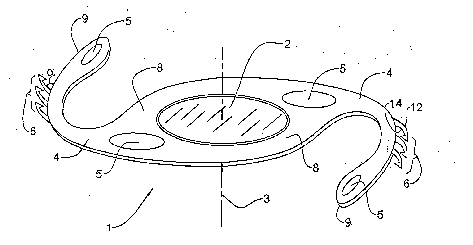
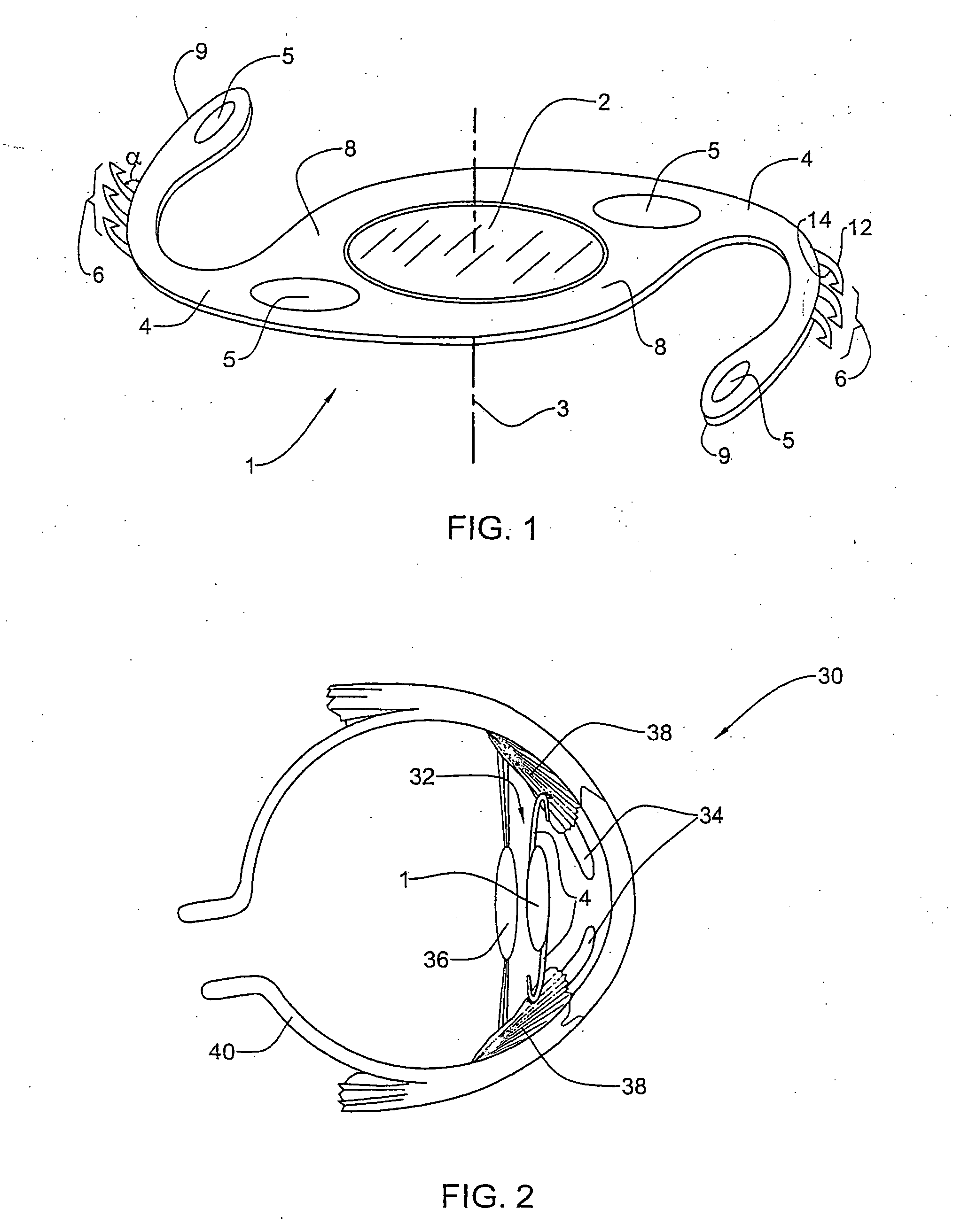
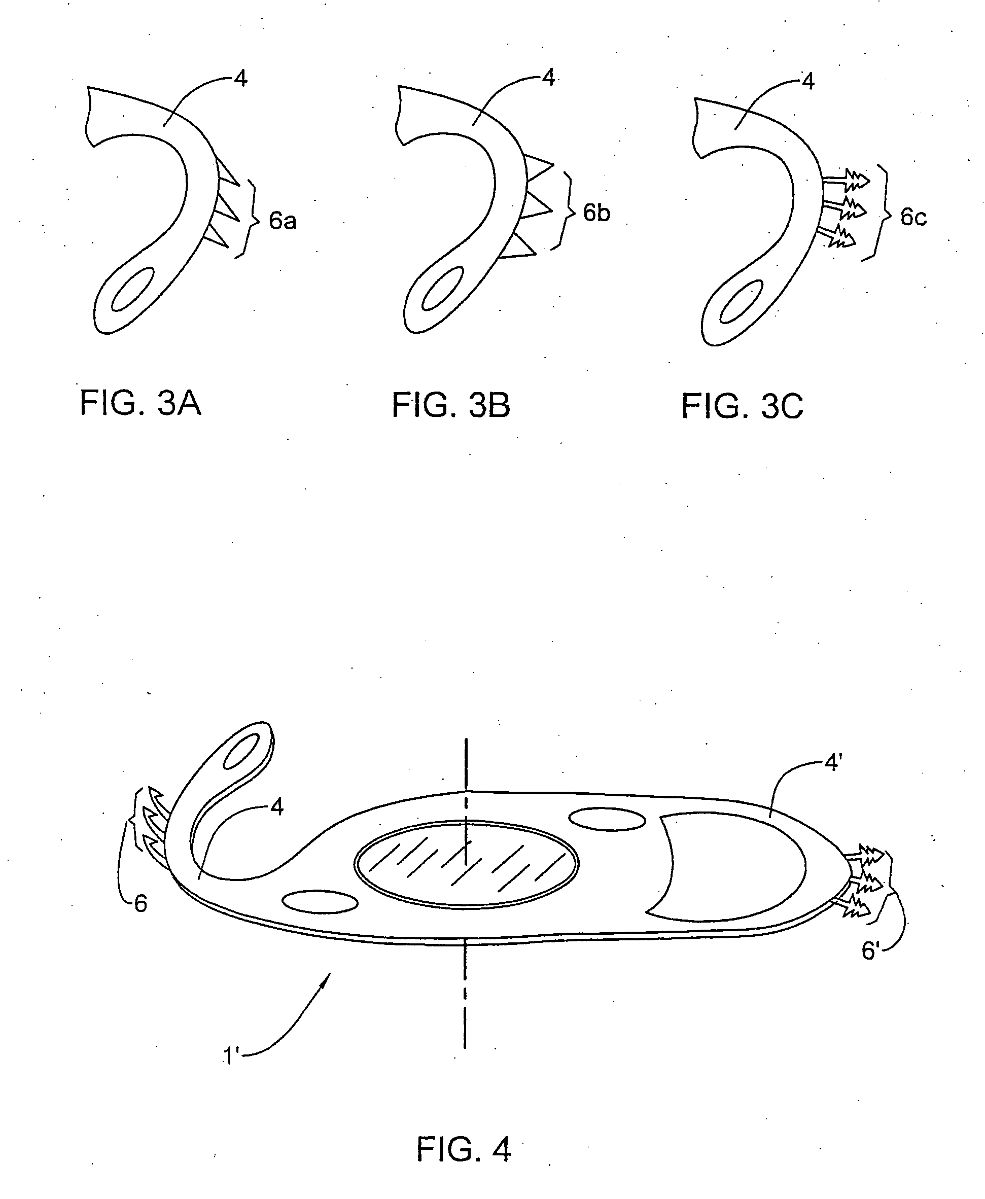
[0015] An intraocular lens system 1 in accordance with one embodiment of the present invention is shown in FIG. 1. The lens system 1 consists of a lens 2 of any known type having an optical axis 3 and two flexible haptics 4 extending away from the circumference of the lens 2. The haptics 4 include longitudinal positioning holes 5 near their base 8 and near their tip 9. These holes 5 aid in the positioning of the lens system 1 and facilitate manipulations thereof. The holes 5 may have any appropriate shape and each haptic 4 may have any number of them at any appropriate location.

[0016] With reference to FIG. 2, the lens system 1 is adapted to be implanted in an eye 30 to replace a cataract. FIG. 2 shows that, when implanted, the lens system 1 is located in the posterior chamber 32 between the iris 34 and the posterior capsule 36, with its haptics 4 bearing against the ciliary sulcus 38 of the scleral wall 40 of the eye 30.

[0017] In accordance with the present invention, and as seen...


PUM


Abstract

An intraocular lens system to be implanted in the posterior chamber of an eye, the system comprises a lens having an optical axis and at least two haptics extending from the circumference of the lens. The two haptics each includes one or more teeth located on their periphery.

Description

FIELD OF THE INVENTION [0001] This invention relates to intraocular lens implantation and particularly to implantation in the posterior chamber of an eye. BACKGROUND OF THE INVENTION [0002] Cataract is clouding of the natural lens of the eye or of its surrounding transparent membrane, which obstructs the passage of light causing various degrees of blindness. To correct this condition, a surgical procedure is known to be performed in which the opaque natural lens, or cataract, is extracted and replaced by an artificial intraocular lens. [0003] The natural lens, located behind the iris in the posterior chamber in front of the vitreous cavity of the eye, is composed of a capsular bag containing gelatinous material. If this bag, called the posterior capsule, is left intact during a cataract extraction procedure, it may serve as a stable support site for implanting an intraocular lens. However, in the course of surgery, the posterior capsule may be inadvertently damaged or removed along ...

Claims


Application Information

Patent Timeline
Patent Type & Authority Applications(United States)
IPC IPC(8): A61F2/16A61F9/013
CPCA61F2/1613A61F2220/0016A61F2002/1681A61F2/16
Inventor NUN, YEHOSHUA BEN
Owner NULENS
Why Eureka
Try Eureka