
Invisible trencher

Inactive Publication Date: 2006-04-06
ORLECK RICHARD JAMES +1
View PDF6 Cites 3 Cited by
  • Summary
  • Abstract
  • Description
  • Claims
  • Application Information

AI Technical Summary

Benefits of technology

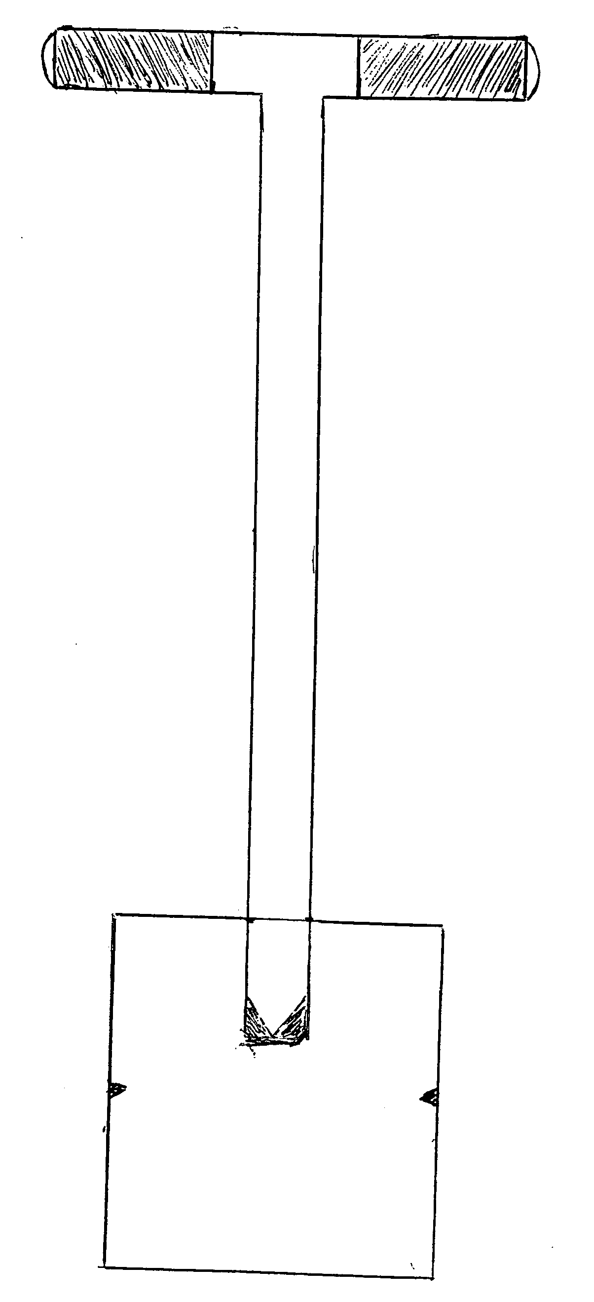
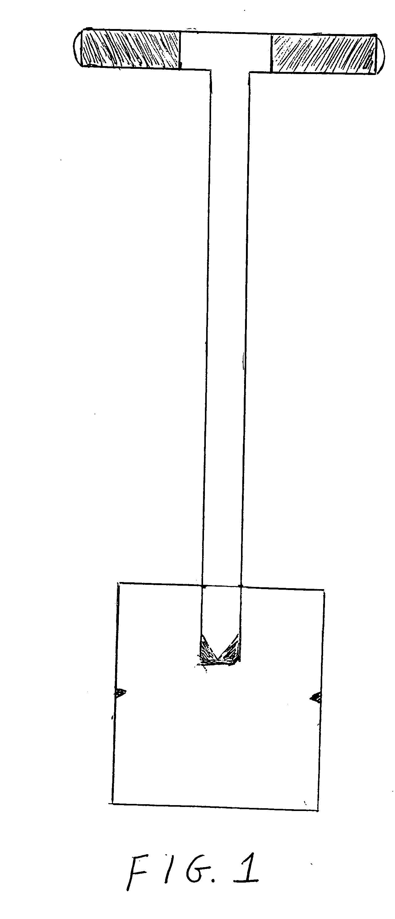
[0007] The bottom of the tool is a steel blade which is a twelve (12) inch square and is one-quarter (¼) inch thick. It is welded to a hollow or concrete filled steel cylinder or shaft after it is fitted into a slit made in the bottom of each side of the cylindrical shaft four and one-half (4½) inches long. The blade is notched on both outer edges at six (6) inches from the bottom of the blade as a guide for the depth required to bury low voltage wires according to the National Electrical Code. The bottom edge of the square blade is grinded to sharpen the tool to assist in piercing the ground.
[0012] The operator places the invisible trencher at the location where the wire, cable, pipe, edging or other reason a narrow, nondisruptive trench may be needed. The invisible trencher is then manually driven into the ground until it pierces the ground. The invisible trencher is then rocked back and forth until the desired depth and width is achieved. Once the item for which the trench was created has been placed in the trench, minimal pressure is needed to close the trench. By minimal pressure, an example would be tamping the open trench on both sides with a foot. After the trench is closed the ground is restored to its near original appearance and generally does not require reconditioning of the trenched area. An invisible trench is created so that reconditioning of the area after trenching is unnecessary. There is very little cost associated with creating the trench and little or no cost in closing the trench.
[0013] The invisible trencher is safe in that there are no power tools connected with the trencher that could cause injury. The weight of the invisible trencher does not create any potential for injury since the maximum weight of the concrete filled shaft is only 22 pounds. Of course proper body mechanics would still be required while operating the tool. Caution would still be required to avoid damaging any existing underground utilities.

Problems solved by technology

Laying underground cables, pipes and wires and trenches for irrigation and other landscaping projects has in modern times required that the area where the trench is needed required extensive disruption of the soil.
Usually this was accomplished by the use of a power tool or manual device that disrupted the ground where the trench was created such that reconditioning of the closed trench area could be extensive and costly.
The manual tools such as the shovel, pick and mattock resulted in a very inaccurate trench width and depth and required extensive disruption to the site where the trench was created.

Method used


Image

  • Invisible trencher
  • Invisible trencher
  • Invisible trencher

Examples


Embodiment Construction

[0028] The Invisible Trencher is a single unit made of three main parts. All three parts are one-quarter (¼) inch cold rolled steel and consist of: 1) a twelve (12) inch square notched at six (6) inches comprises the blade attached to the bottom of the tool; 2) a thirty-two (32) inch long cylinder or shaft with a diameter of 1⅞ inches, which at the bottom is attached the blade and at the top a handle is attached; and 3) the handle is a sixteen (16) inch cylinder with a diameter of 1⅞ inches.

[0029] The parts are welded at the top of the shaft and at the bottom of the shaft to attach the blade and the handle.

[0030] The shaft at the bottom has a 4½ inch slit on each side so that the blade fits into the bottom of the cylinder and then the bottom ends are flattened along the flat side of the blade where the shaft attaches to the blade. A weld is then made sealing the blade to the shaft. The cylinder may or may not be filled with concrete depending on the soil type. Sandy soil would not...


PUM


Abstract

The Invisible Trencher is a single unit tool made of solid steel having a thin square blade welded to the bottom of a hollow or concrete filled metal cylinder with an insulated grip over a handle made of hollow steel welded to the top of the unit. The Invisible Trencher is a hand operated device for creating a trench for multiple purposes such as burying electrical, fiberoptic cable, low voltage wiring, irrigation pipe, etc. underground. The special characteristic of the device is the ability to create a trench without a major disruption in the ground. The trench depth is determined by the amount of force used during manual operation and whether using the hollow or concrete filled unit. The area trenched can be immediately closed with minimal pressure. After closure of the trench the area is restored to a near original appearance without expensive reconditioning of the area.

Description

CROSS-REFERENCE TO RELATED APPLICATIONS [0001] Inventors are not aware of any cross-references. STATEMENT REGARDING FEDERALLY SPONSORED RESEARCH OR DEVELOPMENT [0002] This invention was not made under any federally sponsored research or development. BACKGROUND OF THE INVENTION [0003] Laying underground cables, pipes and wires and trenches for irrigation and other landscaping projects has in modern times required that the area where the trench is needed required extensive disruption of the soil. Usually this was accomplished by the use of a power tool or manual device that disrupted the ground where the trench was created such that reconditioning of the closed trench area could be extensive and costly. [0004] For example a trench was created moving the soil from the area where the trench was needed to a location to the side of the trench or to both sides of the trench. After completing the task the operator was required to close the trench. The soil was then pushed back into the tren...

Claims


Application Information

Patent Timeline
IPC IPC(8): A01B1/00
CPCA01B1/02E02F3/02
Inventor ORLECK, RICHARD JAMESBURKS, JAMES LEE
Owner ORLECK RICHARD JAMES
Learn More