
Snow-gun

a technology of snow-making and snow-guns, which is applied in the field of snow-making, can solve the problems of difficult conversion to ice crystals and the course, and achieve the effect of improving the snow-making efficiency of snow-making guns

Active Publication Date: 2006-04-06
RATNIK IND
View PDF6 Cites 38 Cited by
  • Summary
  • Abstract
  • Description
  • Claims
  • Application Information

AI Technical Summary

Benefits of technology

The technical effect of this invention is to improve the ability of snow guns to make snow more efficiently.

Problems solved by technology

The technical problem addressed in this patent is reducing the costs associated with producing artificial snow using snow-guns, particularly related to the use of compressed air. This is because while some designs may appear efficient based on theory and calculations, their performance can vary greatly when tested in real-life settings due to factors such as weather conditions and equipment quality. Additionally, even slight variations in design features can lead to completely different results.

Method used


Image

  • Snow-gun
  • Snow-gun
  • Snow-gun

Examples


Embodiment Construction

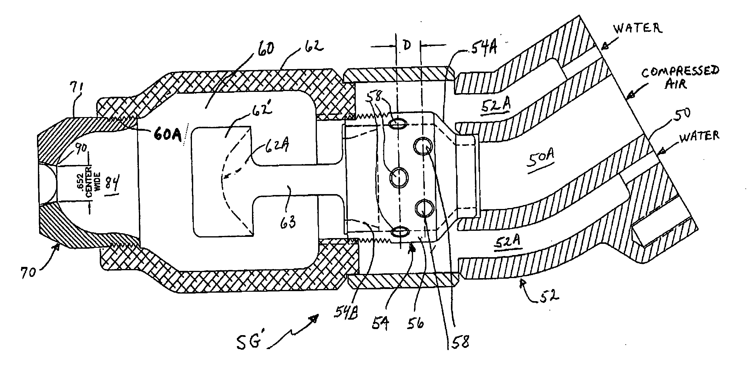
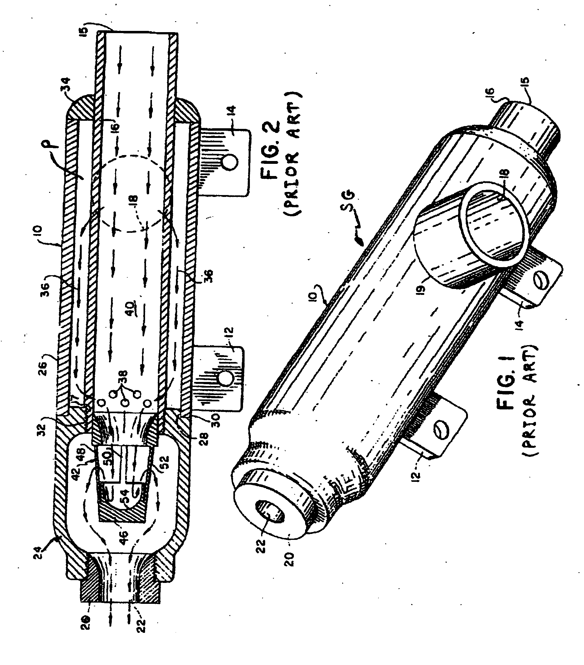
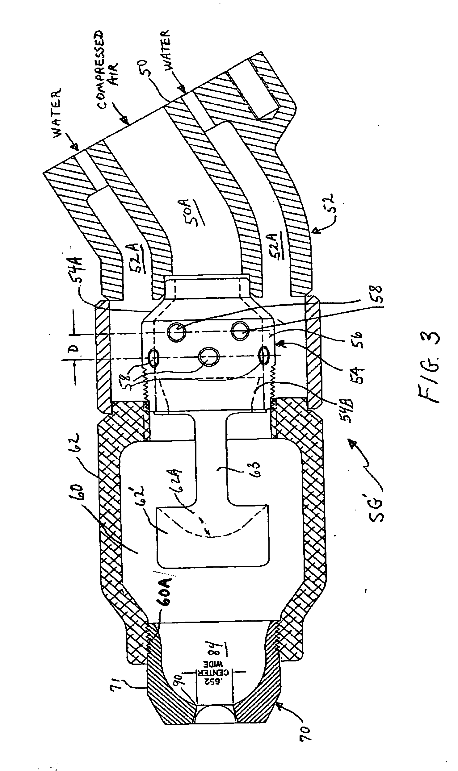
[0016] Referring now to the drawings, FIG. 1 is a perspective view of a conventional snow-gun SG of the type briefly described above and more fully disclosed in the afore-noted U.S. Pat. No. 3,929,013. As described in this patent, such a snow-gun operates to project a plume of man-made snow by injecting relatively small streams of water into a fast-moving air stream that flows axially through the snow-gun housing from a source of compressed air. As explained in the patent, the compressed air stream flowing through the snow-gun acts in concert with certain internal structure of the snow-gun to break-up the injected water streams into relatively small water particles that are readily converted to ice crystals upon being projected into the relatively cold ambient temperature of the surrounding atmosphere. The compressed air stream further serves to rapidly lower the temperature of the injected water streams and, after particle formation, to propel such water particles outwardly, and us...


PUM


Abstract

A snow-gun for producing man-made snow from a combination of compressed air and water features a new nozzle configuration for discharging a mixture of water-particles and air into the surrounding atmosphere. Such nozzle is provided with an elliptically-shaped discharge port having a transverse cross-section that gradually expands in size in the direction in which the air and water particles are discharged from said nozzle. Preferably, the area of the elliptical port changes non-linearly through the front wall of the nozzle, whereby water particles exiting the gun through the nozzle port are less likely to collide with the side walls of the port or with each other before reaching the relatively cold ambient atmosphere.

Description


Claims


Application Information

Patent Timeline
Owner RATNIK IND
Learn More