Image-recording apparatus, and recording-medium supply device

a technology of image recording and supply device, which is applied in the direction of thin material handling, instruments, article separation, etc., can solve the problems of inability to normally eject droplets of ink, gears inevitably have a backlash between the surfaces of meshing teeth, and the above-described power-transmission switching device arranged to shift the idler gear, etc., to achieve high degree of stability, reduce rattling movement, and low cost

Inactive Publication Date: 2006-04-06
BROTHER KOGYO KK
View PDF10 Cites 30 Cited by
  • Summary
  • Abstract
  • Description
  • Claims
  • Application Information

AI Technical Summary

Benefits of technology

[0027] In the recording-medium supply device constructed as described above, the support arm is biased by the biasing device pivotally about the axis of rotation of the drive shaft in a direction for moving the free end portion toward the stack of recording media, so that the rotary medium-supply member is normally held in pressing contact with the top surface of the stack of recording media, irrespective of a height of the stack, whereby the recording media can be fed by the rotary medium-supply member with a high degree of stability.
[0028] Further, the support arm is biased against the support frame by the biasing device also in the axial direction of the drive shaft, so as to reduce a rattling movement of the support arm in the axial direction of the drive shaft and an inclination of the longitudinal direction of the support arm with respect to the medium feeding direction, whereby the recording media can be fed exactly in the medium feeding direction.
[0029] The present recording-medium supply device is available at a relatively low cost owing to simple construction of the biasing device, which is preferably a single torsion spring.

Problems solved by technology

The ink-jet recording head may suffer from a failure to normally eject droplets of ink, due to air bubbles staying within the recording head during its recording operation.
Further, the gears inevitably have a backlash between the surfaces of the meshing teeth, due to limited accuracy of shaping of the gear teeth.
Where the image-recording apparatus is provided with a plurality of medium supply cassettes (e.g., two cassettes), however, the above-described power-transmission switching device arranged to shift the idler gear for selective meshing engagement with the first and second gear trains has a drawback.
However, this type of power-transmission switching device does not permit the drive force to be transmitted to a gear train to drive the medium supply roller for the lower medium supply cassette.
Therefore, another idler gear is necessary to selectively drive the medium supply rollers for the two medium supply cassettes, and the arrangement to selectively transmit the drive force from the same drive motor to the medium supply rollers for the two medium supply cassettes and the maintenance portion tends to be complicated in construction.
A large amount of variation in the position of abutting contact of the medium supply roller with the uppermost cut sheet in the feeding direction with a change of the height of the stack undesirably deteriorates the stability of feeding of the cut sheets from the medium supply cassette.
Where the medium supply cassette has a relatively large storage capacity, the roller support arm has an accordingly large length, so that the rattling movement at the proximal end portion of the support arm is greatly amplified into the rattling movement at the free end portion, whereby the axis of rotation of the medium supply roller is inclined with respect to the direction perpendicular to the feeding direction This inclination prevents the medium supply roller from feeding the cut sheets exactly in the feeding direction, giving rise to a risk of jamming of the fed cut sheets in the feeding path.
Without such auxiliary rollers, an actual path of feeding of the cut sheet fed by the medium supply roller obliquely with respect to the nominal direction of feeding from the cassette greatly deviates from the nominal feeding path between the cassette and registering rollers, resulting in easy jamming of the cut sheet in the feeding path.

Method used


Image

  • Image-recording apparatus, and recording-medium supply device
  • Image-recording apparatus, and recording-medium supply device
  • Image-recording apparatus, and recording-medium supply device

Examples


Embodiment Construction

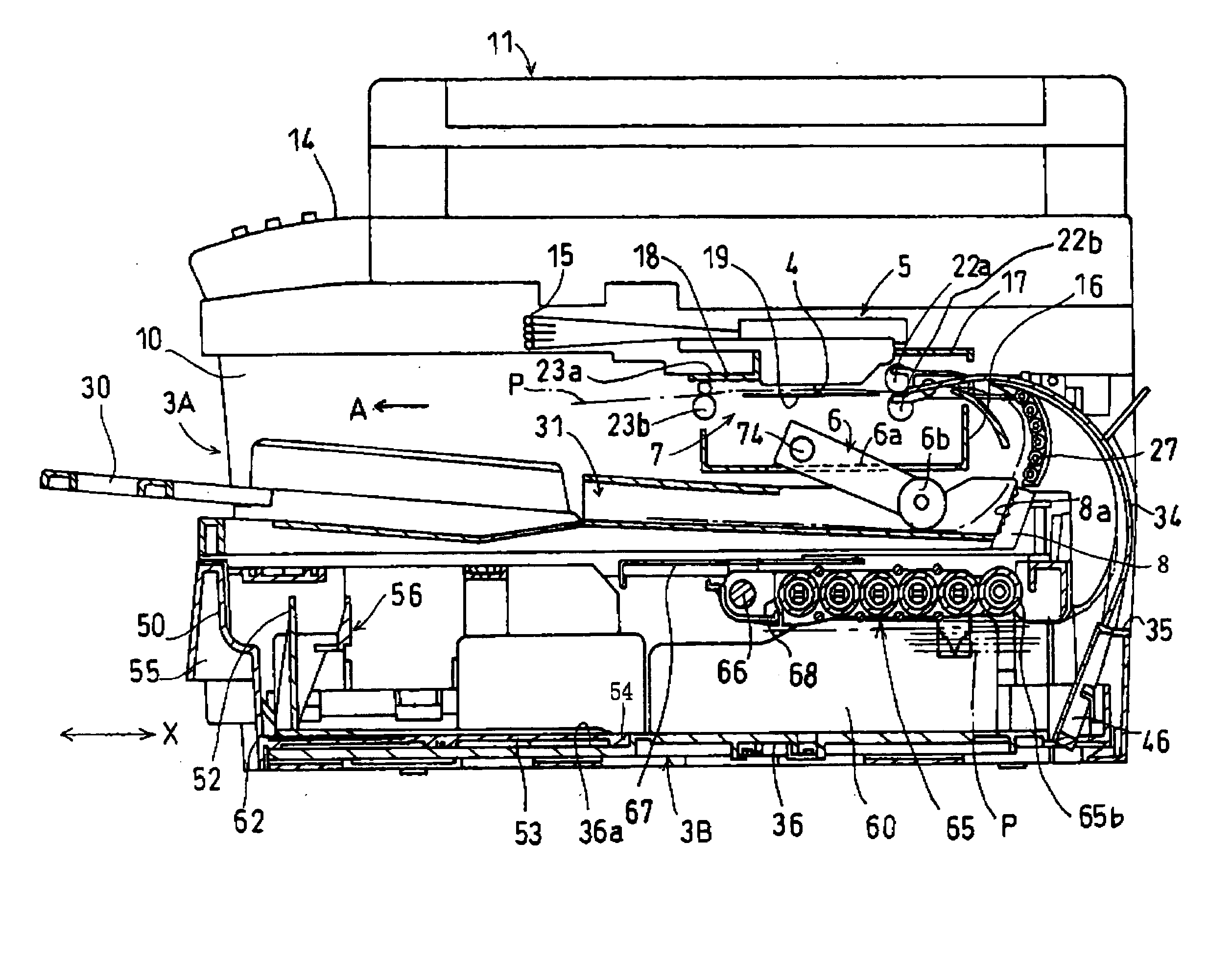
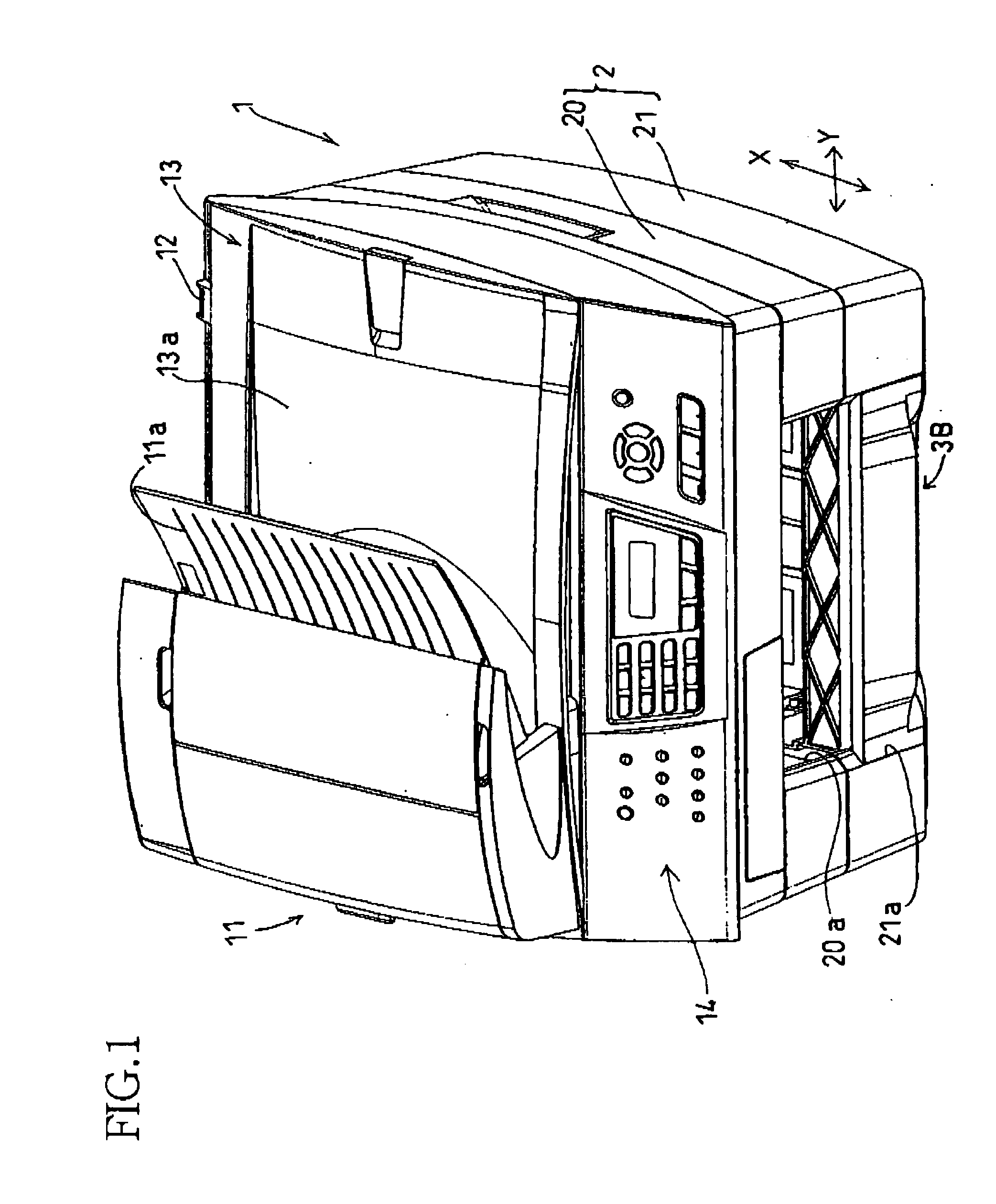
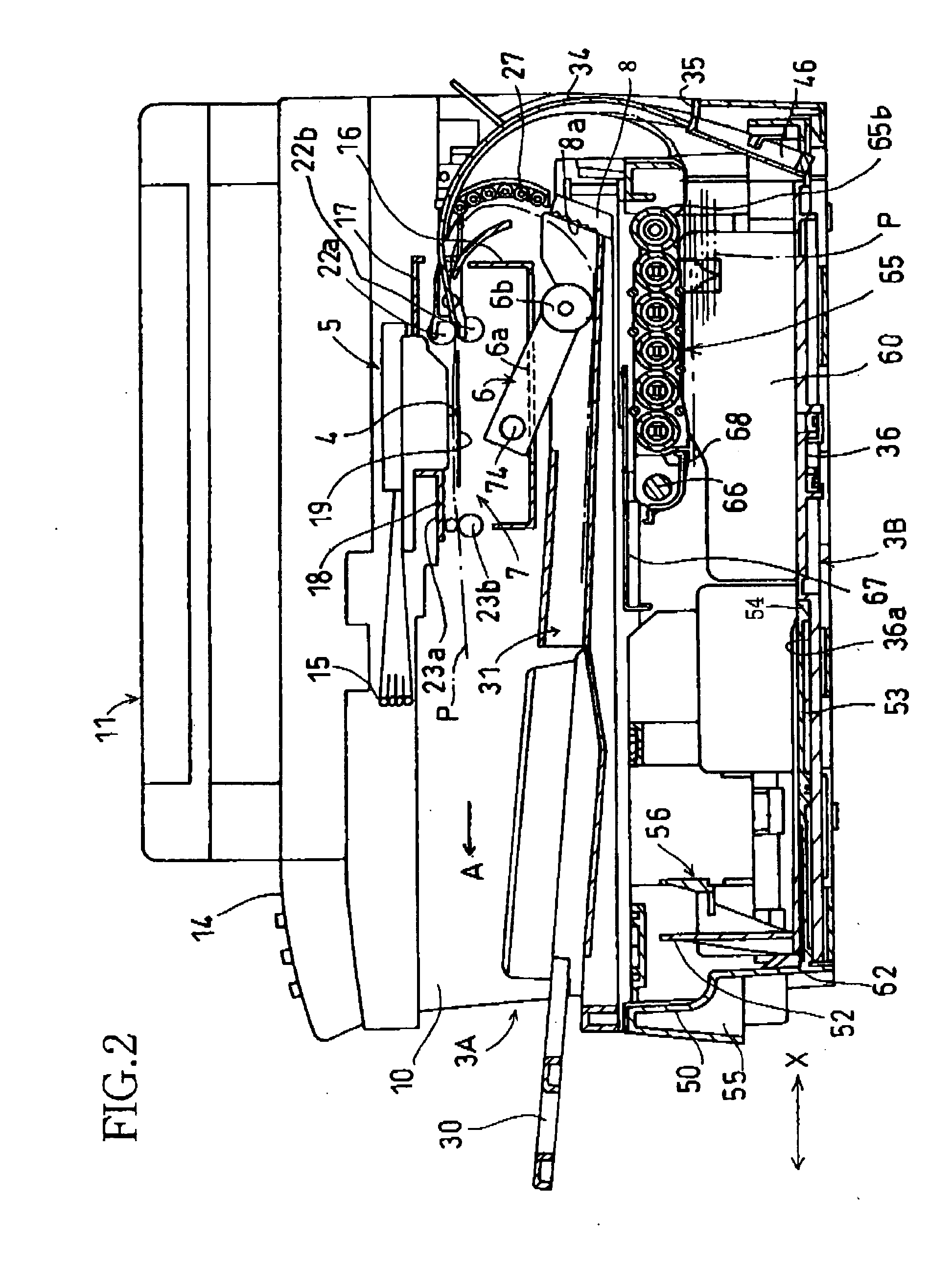
[0062] Referring to FIGS. 1-15, there is shown an image-recording apparatus 1 in the form of a multi-function device constructed according to one embodiment of the present invention, which has a printing function, a copying function, a scanning function and a facsimile function. As shown in FIG. 1, the image-recording apparatus 1 has a housing 2 formed of a synthetic resin and including a first lower casing 20 and a second lower casing 21 which are superposed on each other. The first and second lower casings 20, 21 have respective front openings 20a, 21a at a front end of the housing 2. An upper first sheet supply cassette 3A (shown in FIGS. 2 and 4) is insertable through the front opening 20a into the first lower casing 20, while a lower second sheet supply cassette 3B (shown in FIG. 1) is insertable through the front opening 21a into the second lower casing 21. In the apparatus 1 as shown in FIG. 1, the second sheet supply cassette 3B is accommodated in the housing 2, but the firs...


PUM


Abstract

An image-recording apparatus including (a) a carriage carrying a recording head, (b) a maintenance unit disposed at a standby position located outside a recording area (L) of the recording head, (c) medium feeding devices to feed recording media from respective cassettes (d) first, second and third gears which are disposed outside the recording area and through which a drive force is selectively transmitted from a drive-force output gear to one of the medium feeding devices and the maintenance device, and (e) a power-transmission switching device having a shift gear which is moved for selective meshing engagement with the first, second and third gears according to a distance of movement of the carriage from the recording area toward the maintenance unit. In at least one of the medium feeding devices, a support arm pivotally supported at its proximal end portion by a drive shaft and rotatably supporting a rotary medium-supply member at its free end portion is biased by a biasing device pivotally about the axis of rotation of the drive shaft in a direction for moving the free end portion toward the stack of recording media, and in an axial direction of the drive shaft against a support frame which rotatably supports the drive shaft.

Description

[0001] The present application is based on Japanese Patent Application Nos. 2004-252084 and 2004-268860 respectively filed on August 31 and Sep. 15, 2004, the contents of which are incorporated herein by reference. BACKGROUND OF THE INVENTION [0002] 1. Field of the Invention [0003] The present invention relates in general to a recording-medium supply device arranged to feed recording media such as cut sheets one after another from a stack of the recording media, and an image-recording apparatus such as a printer, a copier and a facsimile device including a recording device and the recording-medium supply device to feed the cut sheets to the recording device. The invention is also concerned with an image-recording apparatus wherein the recording-medium supply device has a plurality of medium supply cassettes each of which is arranged to feed the recording media from a stack of the recording media to the recording device of the apparatus. [0004] 2. Discussion of Related Art [0005] One...

Claims


Application Information

Patent Timeline
Patent Type & Authority Applications(United States)
IPC IPC(8): B65H3/44
CPCB65H3/0669B65H3/44B65H2403/00
Inventor KOZAKI, DAISUKEITO, SHINGO
Owner BROTHER KOGYO KK
Why Eureka
Try Eureka