Shaft seal with lubrication device

a technology of lubrication device and shaft seal, which is applied in the direction of spring/damper, mechanical equipment, engine components, etc., can solve the problems of reducing affecting the sealing effect, so as to improve the effective life of the seal

Inactive Publication Date: 2006-04-06
FREUDENBERG NOK GEN PARTNERSHIP
View PDF29 Cites 25 Cited by
  • Summary
  • Abstract
  • Description
  • Claims
  • Application Information

AI Technical Summary

Benefits of technology

[0005] The present invention includes a seal for use with a reciprocating or rotating shaft. The seal can be used on a suspension fork of a motorcycle, a mountain bike, or other systems with dynamic components requiring sealing. The seal includes a lubrication device that improves the effective life of the seal. The seal also includes an external lip for preventing the accumulation of debris.
[0006] In a preferred embodiment, a shaft seal assembly for use with a reciprocating or rotating shaft includes a shaft seal, a lubricant-storing ring, and a retainer. The retainer and ring can be formed as a subassembly and then combined with a shaft seal. The assembly provides a lubricated shaft and seal that improves performance and the effective life of the shaft seal.

Problems solved by technology

Seals for use with reciprocating or rotating shafts are susceptible to debris and contaminants.
The accumulation of debris at an outer portion of a seal can damage a seal and reduce its effective life.
A problem with a flexible seal, however, is that heat created by friction between the shaft and seal tends to weaken its structure.

Method used


Image

  • Shaft seal with lubrication device
  • Shaft seal with lubrication device
  • Shaft seal with lubrication device

Examples


second embodiment

[0034] a lubricating shaft seal assembly, indicated generally at 100, is illustrated in FIGS. 4 and 5. The seal assembly 100 is particularly designed for use with a reciprocating or rotating shaft 200.

[0035] The shaft seal assembly 100 includes a shaft seal 120, a lubricant-storing ring 130, a retainer 140, a housing 150, and an injector valve 160.

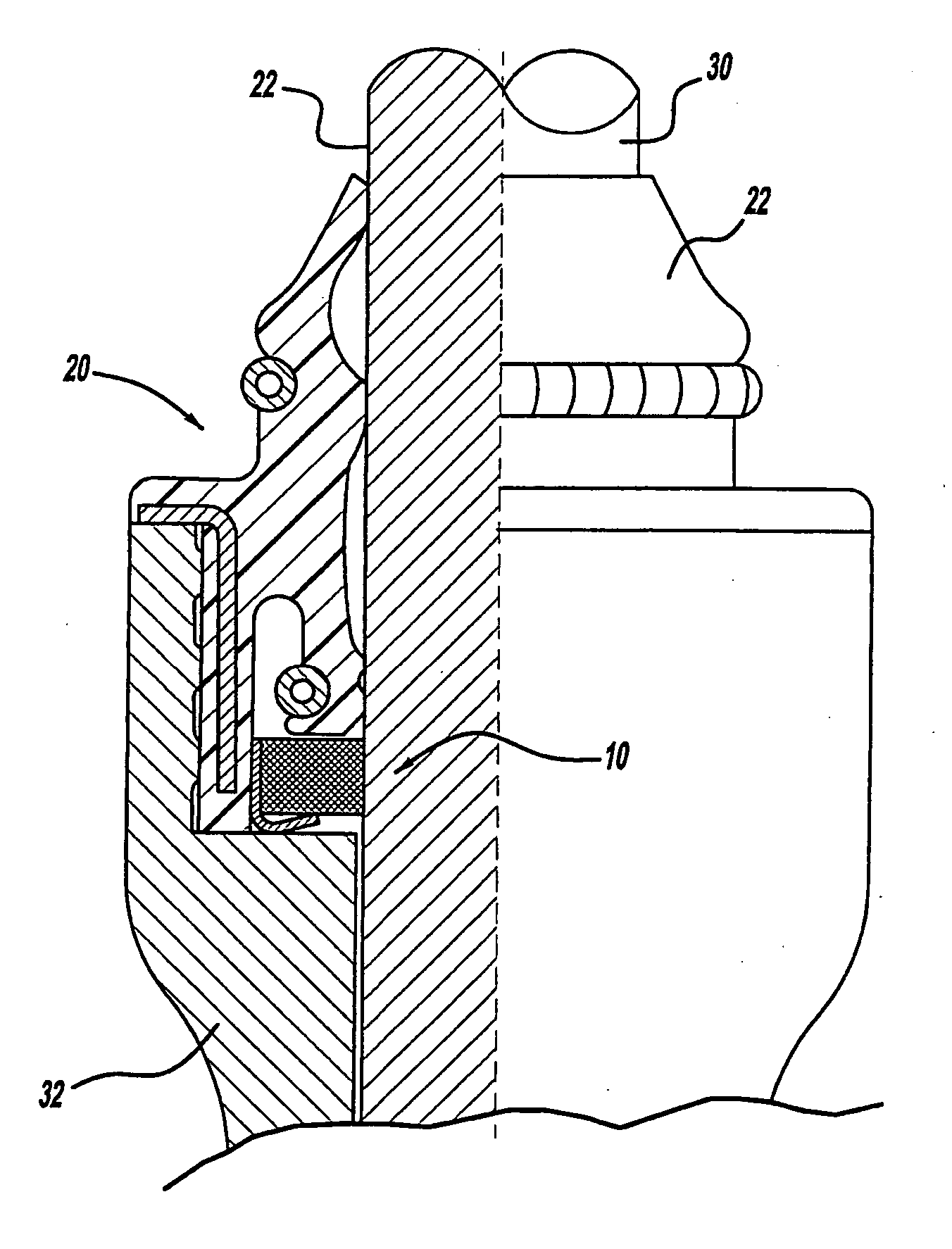
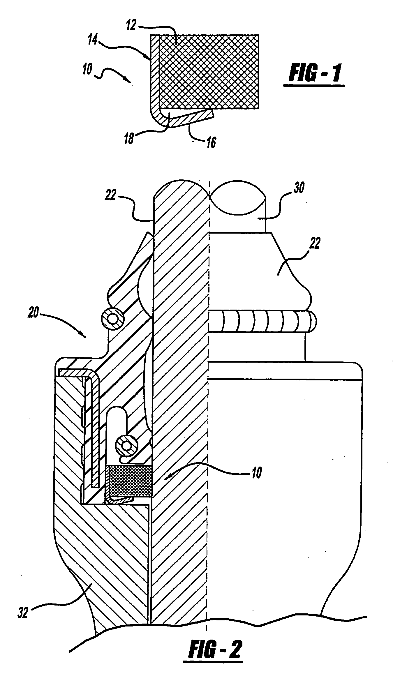
[0036] The shaft seal 120 includes an elastomeric material 122 formed onto an insert 123. The elastomeric material 122 includes a first engagement portion 124 and a second engagement portion 125 that are in contact with the shaft 200. Springs 126 and 127 can be used to enhance the preload or engagement of the shaft seal 120 onto the shaft 200.

[0037] The lubricant-storing ring 130 can be formed from any desired material that wicks-up and retains lubricant, such as foam. Preferably, the ring 130 is formed as an annular member (in one or more pieces) than has an inner circumferential surface 132 in contact with the shaft 200.

[0038] The ret...

third embodiment

[0045] With reference to FIGS. 6-8, a shaft seal assembly 300, according to the principles of the present invention, will now be described. The shaft seal assembly 300 includes a shaft seal 320 formed of an elastomeric material formed onto an insert 323. The elastomeric material includes a first engagement portion 324 and a second engagement portion 325 that are intended to be in contact with a shaft. Springs 126 and 127 are used to enhance the preload or engagement of the shaft seal 320 onto the shaft.

[0046] A lubrication storing ring 330 formed from a foam material or sponge-like material is joined to the seal 320 by an elastomeric retainer 332 which can be integrally molded to the seal element 320 or otherwise attached and / or bonded to the seal element 320. The retainer 323 is formed as an annular ring-shaped member with a mounting portion 334 for mounting the retainer 332 to the over-molded insert portion 323 of the seal member 320. The retainer 332 also includes a radially inwa...


PUM


Abstract

A shaft seal assembly for use with a reciprocating or rotating shaft includes a shaft seal, a lubricant-storing ring, and a retainer. The retainer and ring can be formed as a subassembly and then combined with a shaft seal. The seal includes an annular body portion, a first sealing lip portion, and a first pocket portion. The first sealing lip portion has a substantially uniform axial dimension and is adapted to sealingly engage a shaft. The first pocket portion includes a plurality of pockets, each having an opening toward the first sealing lip portion. The plurality of pockets are each adapted to collect a working fluid when the shaft axially displaces in a first direction and to dispense the working fluid when the shaft axially displaces in a second direction. The assembly provides a lubricated shaft and seal that improves the effective life of the shaft seal.

Description

CROSS-REFERENCE TO RELATED APPLICATIONS [0001] This application is a continuation-in-part of U.S. patent application Ser. No. 10 / 150,886 filed on May 16, 2002 which claims the benefit of U.S. provisional patent applications identified as Application No. 60 / 291,295, filed May 16, 2001 and Application No. 60 / 351,560, filed Jan. 24, 2002. The disclosure of the above application is incorporated herein by reference.FIELD OF THE INVENTION [0002] The present invention relates in general to seals for reciprocating and rotating shafts. In particular, this invention relates to a shaft seal having a lubricant-storing ring and a device for delivering lubricant to the ring. The shaft seal also includes a plurality of pockets for collecting and dispensing a lubricating fluid in response to reciprocal axial displacement of the shaft. BACKGROUND OF THE INVENTION [0003] Seals for use with reciprocating or rotating shafts are susceptible to debris and contaminants. The accumulation of debris at an ou...

Claims


Application Information

Patent Timeline
Patent Type & Authority Applications(United States)
IPC IPC(8): F16J15/32
CPCF16F2230/04F16J15/324F16J15/3252
Inventor DOWNES, MICHAEL D.LAPLANTE, ROBERT P.
Owner FREUDENBERG NOK GEN PARTNERSHIP
Why Eureka
Try Eureka