Office chair

a technology for office chairs and backrests, applied in the field of office chairs, can solve the problems of uncomfortable pulling of user's clothing, none have comprehensively addressed the overall body posture, relative positioning of body parts, configuration and material of seats and/or backrests, etc., and achieve the effect of limiting the tilting of the sea

Inactive Publication Date: 2006-04-06
HERMAN MILLER INC
View PDF99 Cites 23 Cited by
  • Summary
  • Abstract
  • Description
  • Claims
  • Application Information

AI Technical Summary

Benefits of technology

[0010] In one aspect of the invention, a linkage assembly is adapted to allow the seat and back to tilt downwardly and rearwardly and to allow pivotal movement of the seat about a pivot axis in substantial alignment with the hip joints of a user to inhibit shear forces from pulling the clothing on the body of a user.
[0015] In a preferred embodiment of the invention, the linkage assembly includes a pair of first inks having an end pivotally attached to the lateral portions of the seat to define a pivot axis in substantial alignment with the hip joints of a user. A pair of second links have a first section rigidly connected to the first links and the back and a second section angled downwardly from the first section. The second section terminates in an end pivotally mounted to a forward portion of the base member. A restraining link has one end pivotally attached to a rear portion of the seat and another end pivotally attached to the base member to limit tilting of the seat. The first links, second links, and restraining links are configured to create an effective pivot point of the seat at substantially the ankles of a user having feet resting on a floor. Thus, the seat pivots about the hip axis of a user such that the angle therebetween increases as the back and seat tilt rearwardly.
[0016] The chair preferably includes a bowed section to support the lumbar region of a back of a user. The greater rearward tilting of the back relative to the seat automatically lowers the bowed section to accommodate the changing position of the lumbar region of the user.
[0019] The embodiments of the present invention provide significant advantages over other tiltable office chairs. For example, in the most preferred embodiment, the seat and back naturally conform to the body of a user during tilting of the chair to thereby reduce shear forces acting on the thighs and trunk of the user and minimize pressure acting on the underside of the user's thighs at the knees. This chair also automatically supports the body of the user in ergonomically desirable positions for performing tasks of varying intensity. The user's weight is distributed evenly and shifts of the center of gravity are compensated for to allow the user to maintain equilibrium and good balance. Thus, the user's body is positioned to reduce fatigue, allow proper alignment for performing various tasks, achieve maximum alertness or relaxation, and ensure overall comfort. Moreover, the range of vertical adjustment of the chair is increased to allow a lower minimum height and higher maximum height than conventional office chairs.

Problems solved by technology

These shear forces tend to cause an uncomfortable pulling of the user's clothing.
Although some tilting chairs have incorporated such an ankle tilt feature, none have comprehensively addressed the overall body posture and relative positioning of body parts for ensuring comfort and minimizing fatigue regardless how intensely a user works.
A related disadvantage of conventional office chairs is the configuration and material of the seat and / or backrest.
However, a deformable cushion does not provide a self-adjusting support which varies according to the position of the user and the tilt position of the seat.
Such seating also tends to provide insufficient aeration since it acts as another layer of clothing.
The membrane of such a seat is difficult to repair and / or replace since the chair would typically have to be disassembled to allow such maintenance.
In addition, the structural requirements of such an attachment limits the shape and size of the frame and the membrane.
Typically, it is difficult to exceed this range of height adjustment with seats which tilt about the knees or ankles of a user.
Because such “ankle tilt” and “knee tilt” chairs have relatively large tilt housings, it is difficult to provide a lower minimum and higher maximum seat height while maintaining the required overlapping distance between the tubes.

Method used


Image

  • Office chair
  • Office chair
  • Office chair

Examples


Embodiment Construction

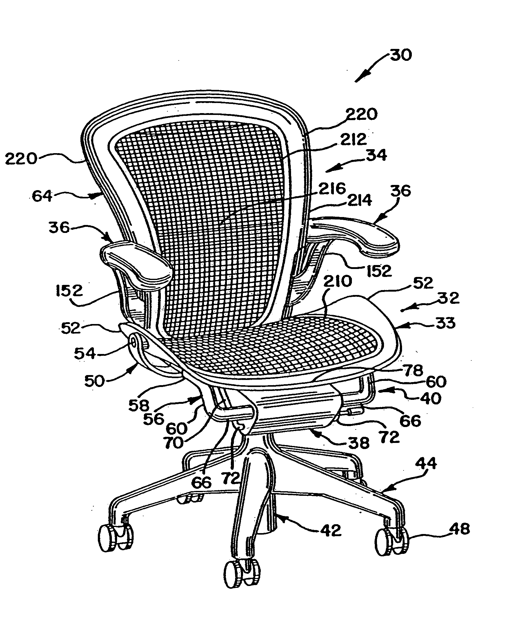
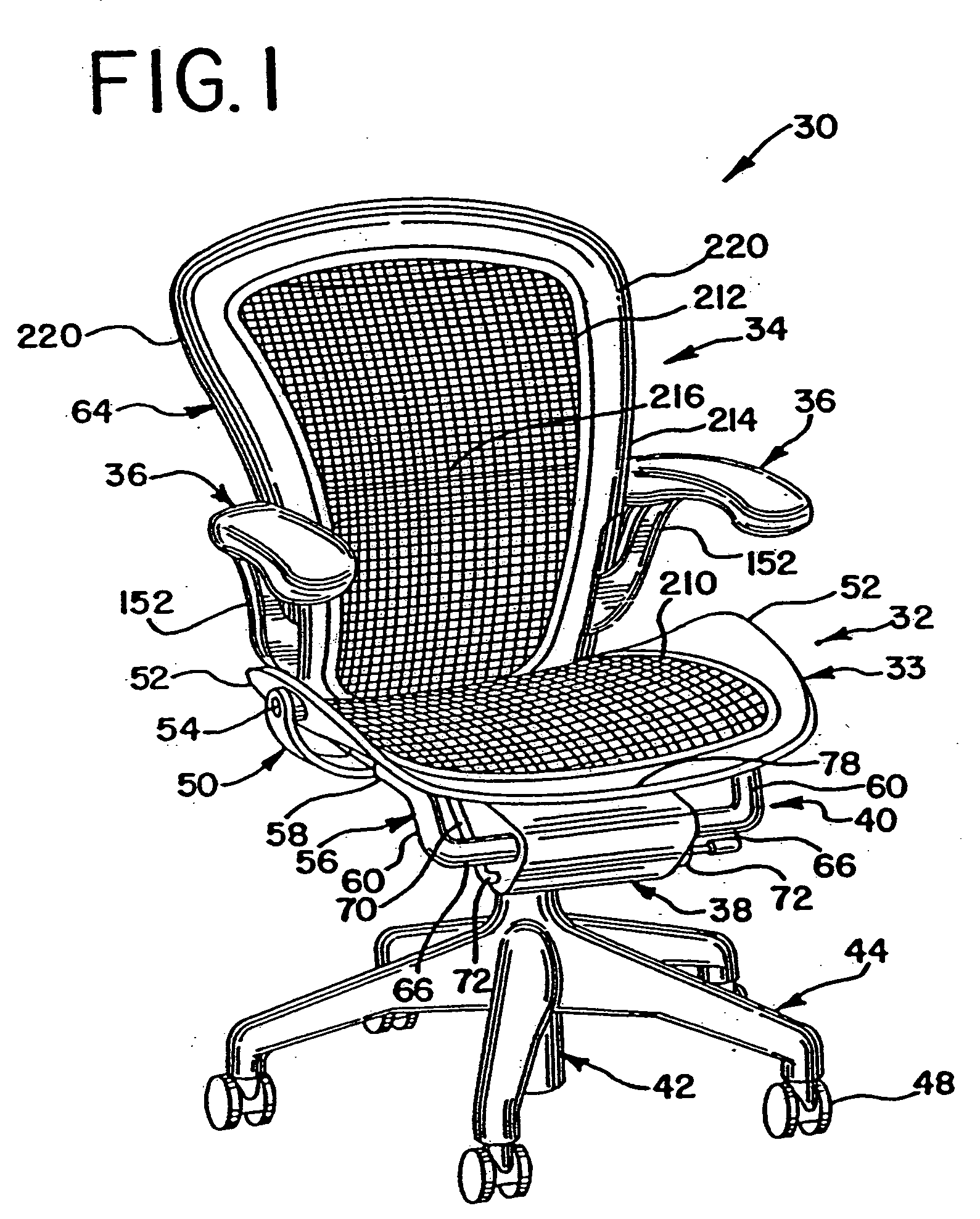
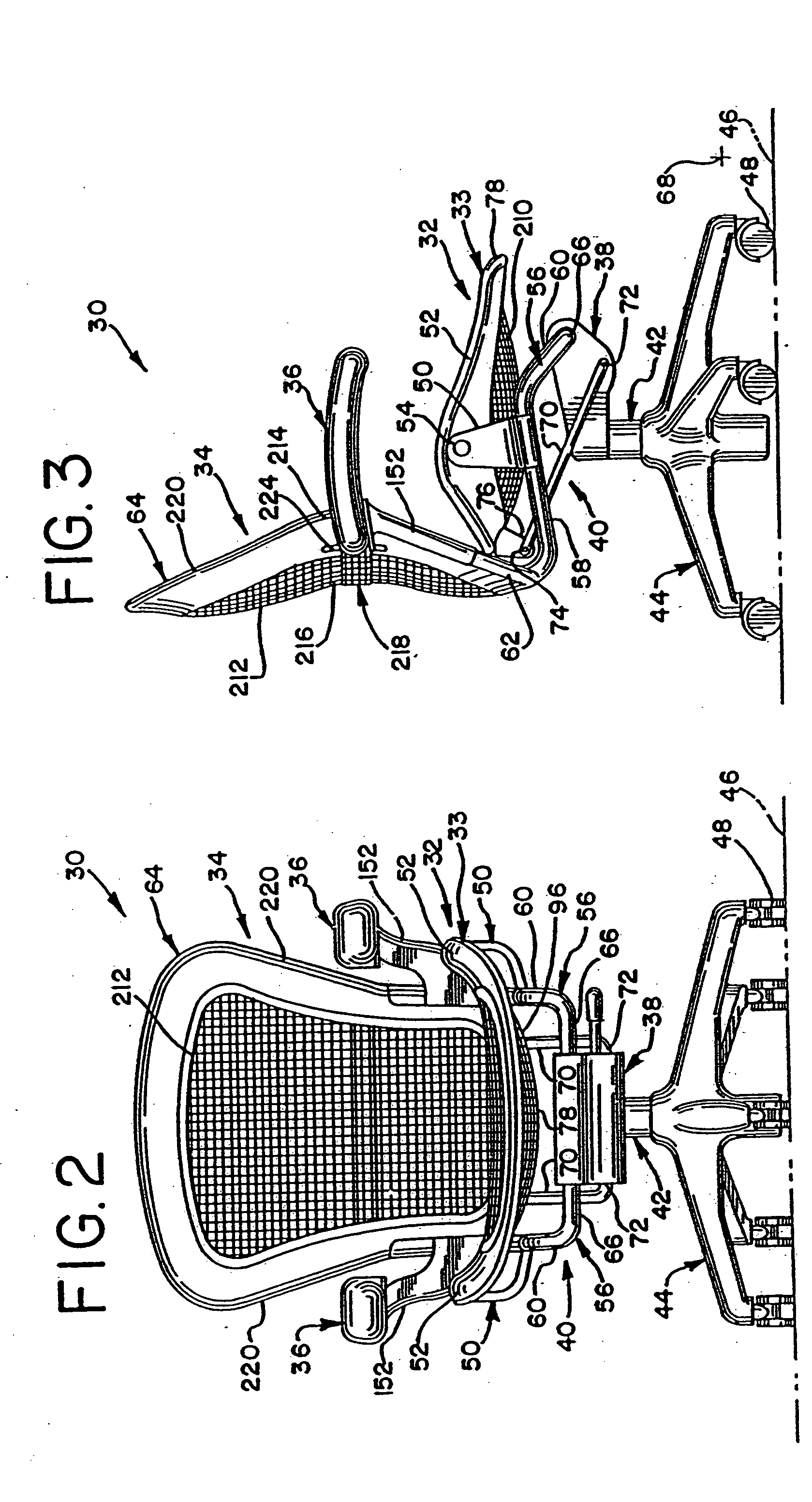
[0072] Referring to the drawings, FIGS. 1-7 show a preferred embodiment of a chair 30 in a middle tilt position. The chair 30 includes a seat 32, a backrest 34, and a pair of armrest assemblies 36. The seat 32 and backrest 34 are connected to a tilt control housing 38 by a linkage assembly 40. The tilt control housing 38 is mounted on a vertically adjustable, dual stage support column 42 which is secured to the center of a pedestal 44. The pedestal 44 is movably supported on a floor 46 by a plurality of casters 48 or the like.

[0073] In a preferred embodiment of the invention, the linkage assembly 40 includes a pair of first links 50 pivotally attached to upwardly extending side portions 52 of a seat frame 33 at pivot points 54 to define a pivot axis at substantially the hip joints of a user. A pair of second links 56 each have a substantially straight first section 58 to which the first links 50 are fixedly attached and a second section 60 angled downwardly from the first section 5...


PUM

PropertyMeasurementUnit
angleaaaaaaaaaa
angleaaaaaaaaaa
angleaaaaaaaaaa

Abstract

A chair includes a control housing, a seat and a back support including an upwardly extending upright portion and a link portion extending forwardly from a lower portion of the upright portion. The link portion is pivotally connected to the control housing about a first pivot axis. The seat is connected to the link portion and is pivotable relative thereto. A linkage is coupled to the seat and is pivotally connected to the control housing at a second pivot axis positioned rearwardly and downwardly from the first pivot axis.

Description

RELATION TO OTHER APPLICATIONS [0001] This application is a continuation of U.S. patent application Ser. No. 10 / 772,935, filed Feb. 5, 2004, which is a of continuation of U.S. patent application Ser. No. 10 / 256,671, filed Sep. 27, 2002, which is a continuation of U.S. patent application Ser. No. 09 / 859,694, filed May 17, 2001, which is a continuation of U.S. patent application Ser. No. 08 / 347,475, which was the National Stage of International Application No. PCT / US93 / 05731, filed Jun. 15, 1993, which is a continuation-in-part of U.S. patent application Ser. No. 07 / 898,907, filed Jun. 15, 1992, the entire disclosures of which are incorporated herein by reference.BACKGROUND OF THE INVENTION [0002] The present invention relates generally to office chairs, and more particularly, to a height-adjustable, tiltable office chair which supports the body of a user in ergonomically desirable positions for performing various tasks. [0003] Office chairs are typically configured to allow tilting o...

Claims


Application Information

Patent Timeline
Patent Type & Authority Applications(United States)
IPC IPC(8): A47C1/024A47C7/32A47C1/026A47C1/03A47C1/032A47C1/035A47C3/00A47C3/025A47C3/026A47C3/18A47C3/20A47C3/24A47C3/26A47C3/30A47C3/40A47C5/02A47C7/00A47C7/02A47C7/14A47C7/24A47C7/28A47C7/40A47C7/54A47C23/14A47C27/12A47C31/00B29C45/14B68G11/00D03D1/00D03D9/00D03D13/00F16M11/28
CPCA47C1/03Y10T29/49998A47C1/03255A47C1/03261A47C1/03266A47C3/30A47C5/06A47C7/022A47C7/14A47C7/282A47C7/40B29C45/14065B29C45/14631B29K2713/00B29L2031/443Y10T29/49863Y10T29/4998Y10T403/32475Y10T29/49867A47C1/03238A47C7/029Y10T442/3024A47C1/0303A47C7/02
Inventor STUMPF, WILLIAM E.SCHOENFELDER, RODNEY C.CHADWICK, DONALDMAALOUF, CAROLYNCOFFIELD, TIMOTHY P.SAYERS, RANDY J.BRUNER, JEFFREY W.CAMMENGA, ERIC
Owner HERMAN MILLER INC
Why Eureka
Try Eureka