Unlock instant, AI-driven research and patent intelligence for your innovation.

Printer, and method for controlling print controller

a technology of printers and controllers, applied in the field of printers, can solve the problems of low general versatility of drivers

Active Publication Date: 2006-04-06
SEIKO EPSON CORP
View PDF13 Cites 11 Cited by
  • Summary
  • Abstract
  • Description
  • Claims
  • Application Information

AI Technical Summary

Benefits of technology

[0011] The printing device can derive control constants on the basis of the print setting information input by the host machine. Consequently, general versatility of a driver can be enhanced.
[0018] As a result, the method becomes compatible with a printing device which cannot derive control constants. Specifically, the method can be embodied as a driver having high general versatility.
[0030] By adoption of such a program, the present invention can cope with a printing device which cannot derive control constants; namely; the program can be embodied as a highly-versatile driver.

Problems solved by technology

However, in the above related-art configuration, the data unique to the model of the printer are supplied from the outside of the printer, and hence there arises a problem of general versatility of a driver being low.

Method used


Image

  • Printer, and method for controlling print controller
  • Printer, and method for controlling print controller
  • Printer, and method for controlling print controller

Examples


first embodiment

[0053] A first embodiment embodying the present invention will be described hereinbelow by reference to FIGS. 1 to 7.

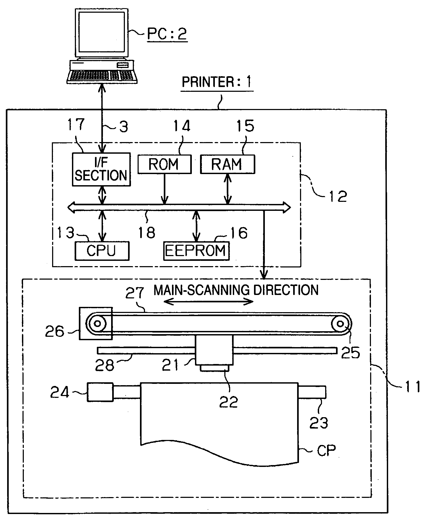
[0054]FIG. 1 is a perspective view showing the appearance of a printing device according to the present embodiment. This printing device is an inkjet printer 1 capable of outputting a color image, and performs printing on the basis of print data transmitted from a personal computer (hereinafter abbreviated as “PC”) 2 serving as a host machine. In the present embodiment, the printer 1 and the PC 2 are connected together by way of, e.g., a USB cable 3.

[0055] A paper feeder 5 is provided on the back of a main body 4 of the printer 1, and a printing medium which can undergo printing performed by the printer 1 is fed from the paper feeder 5 to the inside of the main body 4. In the present embodiment, cut paper, which is employed as a cut sheet, set in a sheet feeder 5a or rolled paper—being set in a rolled-paper support section 5b and serving as long paper—is fed to the ...

second embodiment

[0092] A second embodiment of the present invention will be described hereinbelow by reference to the drawings.

[0093] First, there will be described a diagrammatic configuration of an inkjet recorder, which is an example of the “recorder” of the present invention.

[0094]FIG. 10 is a plan view of the principal section of an inkjet recorder of the present invention. FIG. 11 is a side view. FIG. 12 is a schematic block diagram of a recording system of the present invention.

[0095] In an inkjet recorder 250, a carriage 261 is supported by a carriage guide shaft 251 so as to be movable in a main-scanning direction X, as “main scan drive means” for causing a recording head 262—which performs recording by ejecting ink to recording paper P used as a “recording material”—to scan in the main-scanning direction X with respect to the recording paper P. The carriage 261 is equipped with the recording head 262 and a PW sensor 234 to be described later. Rotational drive force of a CR motor 263 (F...


PUM


Abstract

A printer 1 has an I / F section 31 for receiving data from a PC 2, a parameter-deriving section 35b for deriving a control constant on the basis of print setting information included in the received data, and a printer section 11 which performs printing operation on the basis of the print setting information, the control constant, and print data included in the received data.

Description

[0001] The present invention relates to a printer which subjects print data to printing through use of parameters, as well as to a method for controlling a print controller which controls the printer. [0002] Conventionally, when printing is carried out by connecting a printing device, such as a printer, to a host machine, such as a personal computer (PC), a printer driver compatible with the printer is generally installed in the PC, and printing is performed on the basis of the print data output by means of the printer driver. More specifically, the printer driver converts into print data image data to be printed by the printer. When the print data are transmitted from the PC to the printer, the printer carries out printing on the basis of the thus-received print data. Model-specific parameters are attached to the print data as control parameters which are used when print data are subjected to printing. The printer carries out printing by use of these model-specific parameters. [000...

Claims


Application Information

Patent Timeline
Patent Type & Authority Applications(United States)
IPC IPC(8): B41J29/38
CPCB41J29/393G06K15/00G06K15/1805G06K15/1809
Inventor YASUE, TAKUYASHIMA, SHUICHINOMURA, REIKO
Owner SEIKO EPSON CORP
Features
  • R&D
  • Intellectual Property
  • Life Sciences
  • Materials
  • Tech Scout
  • Unparalleled Data Quality
  • Higher Quality Content
  • 60% Fewer Hallucinations
Learn More