Lithographic apparatus and position measuring method

a position measurement and lithographic technology, applied in the field of lithographic apparatus and methods, can solve the problems of difficult to measure absolute pressure with high accuracy with conventional pressure sensors, limited accuracy of alignment, and difficulty in measuring absolute pressure with conventional pressure sensors. achieve the effect of accurately measuring the position of objects in ambient spa

Active Publication Date: 2006-04-06
ASML NETHERLANDS BV
View PDF9 Cites 12 Cited by
  • Summary
  • Abstract
  • Description
  • Claims
  • Application Information

AI Technical Summary

Benefits of technology

[0022] Embodiments of the invention include a method and an apparatus for measuring a position of an object

Problems solved by technology

In an initialization phase, the accuracy of the alignment may be limited, since possible position offsets may be corrected by using alignment sensors for scaling on alignment marks previously provided on the mask and the substrate, or on the carriers thereof.
Since, in the initialization phase, a scaling

Method used


Image

  • Lithographic apparatus and position measuring method
  • Lithographic apparatus and position measuring method
  • Lithographic apparatus and position measuring method

Examples


Embodiment Construction

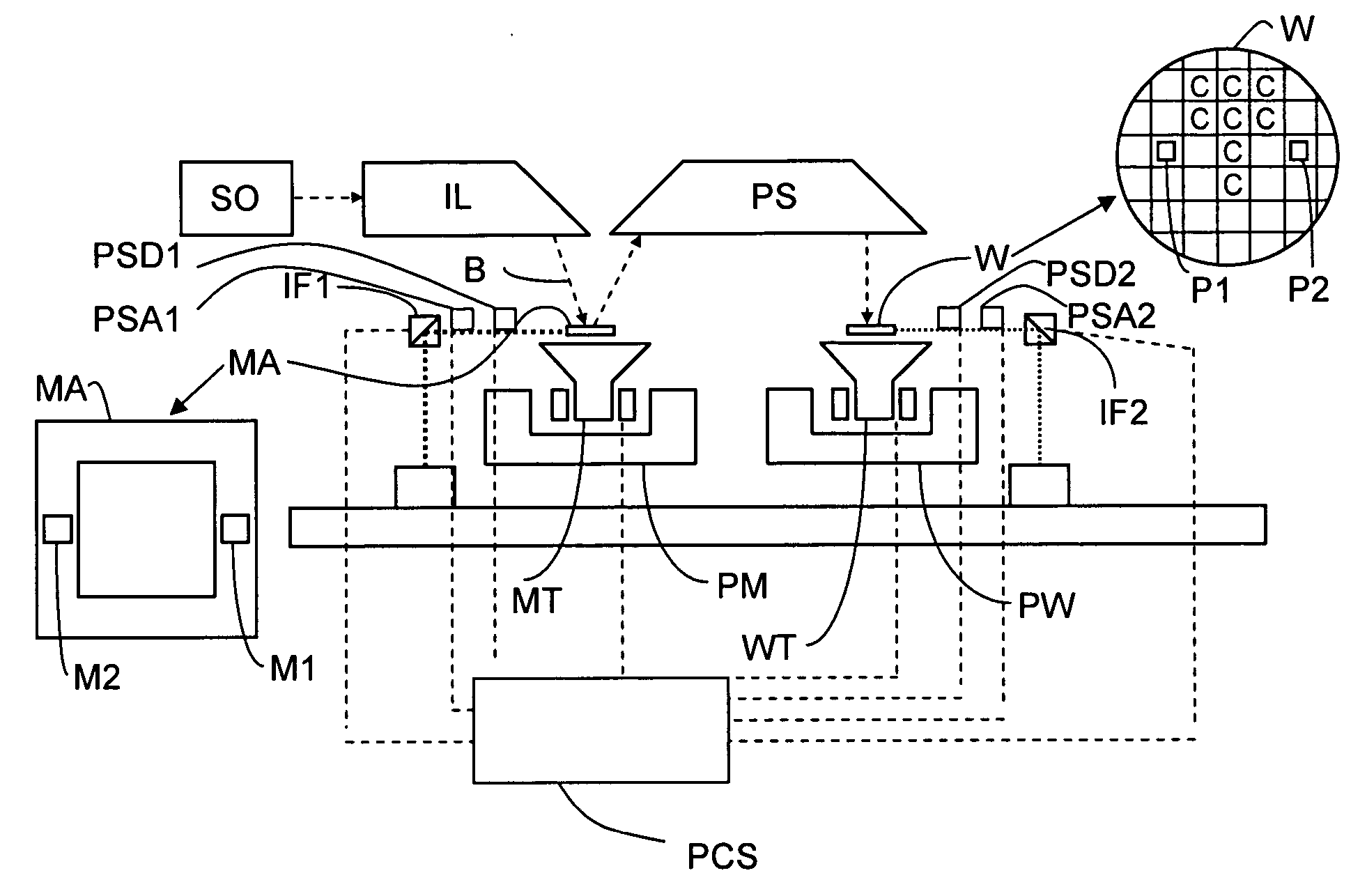
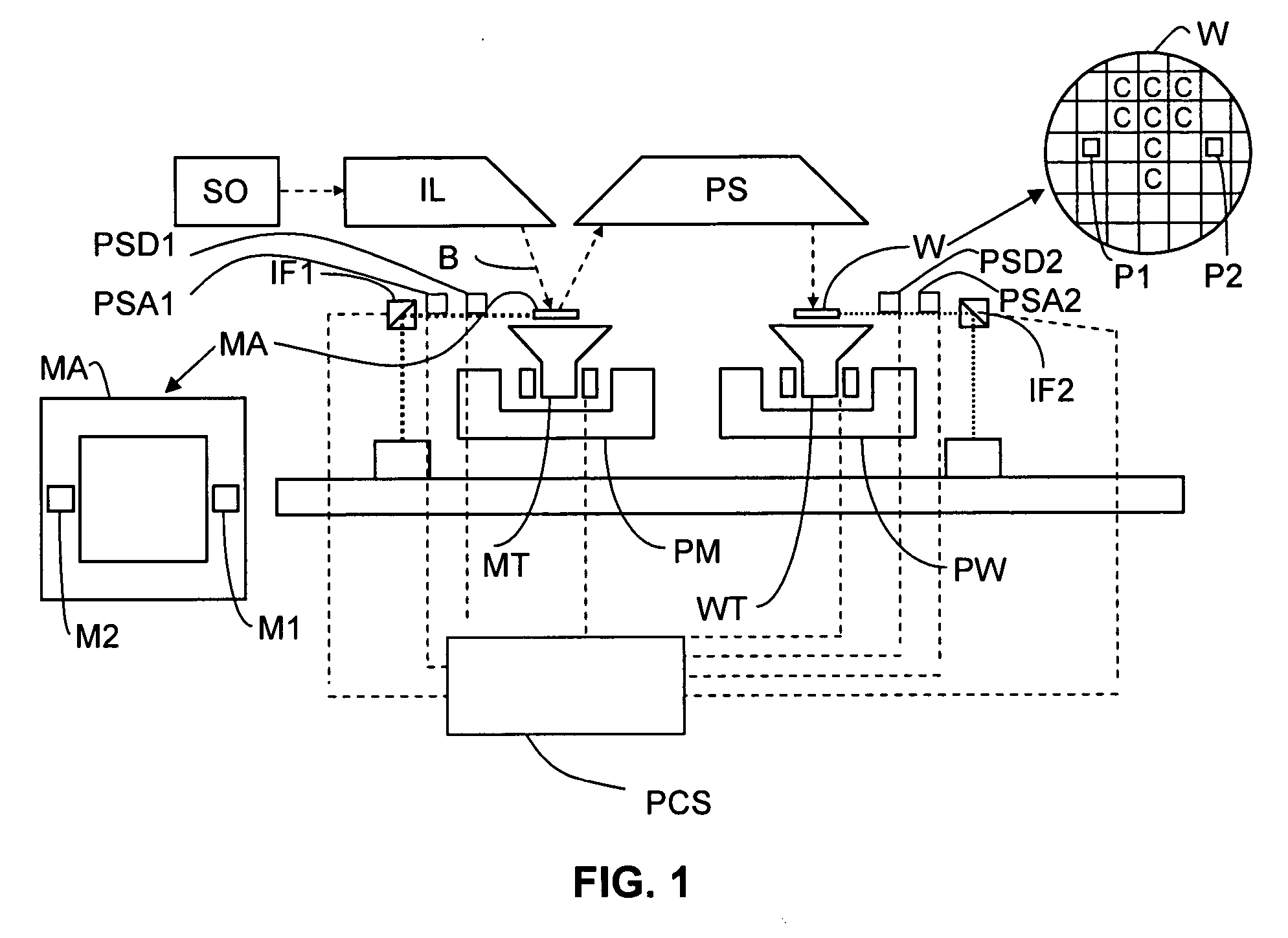
[0037]FIG. 1 schematically depicts a lithographic apparatus according to one embodiment of the invention. The apparatus includes an illumination system (illuminator) IL configured to condition a radiation beam B (e.g. UV radiation or another suitable type of radiation) and a support structure or patterning device support (e.g. a mask table) MT configured to support a patterning device (e.g. a mask) MA and connected to a first positioning device PM configured to accurately position the patterning device in accordance with certain parameters. The apparatus also includes a substrate table or substrate support (e.g. a wafer table) WT configured to hold a substrate (e.g. a resist-coated wafer) W and connected to a second positioning device PW configured to accurately position the substrate in accordance with certain parameters, and a projeection system (e.g. a refractive projection lens system) PS configured to project a pattern imparted to the radiation beam B by patterning device MA on...


PUM


Abstract

In a lithographic apparatus, a measurement of the position of an object in an ambient space by an object position measuring system which is influenced by pressure variations in the ambient space, is corrected by an accurate measurement of the pressure in the ambient space. A reference pressure volume may be provided, having a fluid connection with predetermined flow characteristics to the ambient space. A pressure difference is measured between a pressure in the reference pressure volume and an ambient pressure in the ambient space. The absolute pressure in the reference pressure volume is added to the pressure difference to determine a change of pressure in the ambient space. Alternatively, the pressure difference is integrated over time for determining a change of pressure in the reference pressure volume, and this change of pressure in the reference pressure volume is added to the pressure difference to determine a change of pressure in the ambient space. The fluid connection may also be a valve which can be opened and closed.

Description

BACKGROUND [0001] 1. Field of the Invention [0002] The present invention relates to lithographic apparatus and methods. [0003] 2. Description of the Related Art [0004] In order to determine a position of an object very accurately, an object position measuring system, such as a laser interferometer system, may be used. In a laser interferometer system, which is an incremental system where the wavelength of the laser light used constitutes a measurement unit, a reflection of a laser beam against a reflecting surface of the object is measured and compared with an internal reference path. If the object position changes in line with the laser beam, the comparison between the reference and the measuring laser beam will show a number of interference transitions (consisting of constructive / destructive interference between the measuring path and the reference path) which is proportional to the displacement. The number of interference transitions is not only proportional to the displacement, ...

Claims


Application Information

Patent Timeline
IPC IPC(8): G03B27/42
CPCG03F7/70775G03F7/70858G03F7/20G03F9/00
Inventor EUSSEN, EMIEL JOZEF MELANIEVAN-EMPEL, TJARKO ADRIAAN RUDOLFPRIL, WOUTER ONNO
Owner ASML NETHERLANDS BV
Why Eureka
Try Eureka