
Data transmission system, data transmitter, and transmitting method

Inactive Publication Date: 2006-04-06
PANASONIC CORP
View PDF7 Cites 22 Cited by
  • Summary
  • Abstract
  • Description
  • Claims
  • Application Information

AI Technical Summary

Benefits of technology

[0030] Even if a plurality of data transmission devices are connected via a transmission line so as to form a ring structure and transmission and reception is made impossible at a certain portion, a data transmission system according to the present invention enables communication between a master and a portion where electrical communication is impossible. In addition, a data transmission device which is located most upstream in electrical communication from the portion, in electrical communication performed in a single direction toward the portion where electrical communication is impossible, can be easily detected based on absence of data reception from the transmission line, and setting that data transmission device as a master makes it possible to communicate with another data transmission device.
[0034] Also, the data transmission method and the data transmission device according to the present invention make it possible to achieve an effect similar to that achieved by the above-described data transmission system.

Problems solved by technology

In other words, neither the establishment of clock synchronization throughout the network nor the setting of the determination levels is achieved, and therefore the above-described initialization operation is not completed successfully, thus preventing each of the data transmission devices 100a to 100n from performing data communication.
Thus, in the case where the above-described problem has arisen, each of the connected-devices connected to the network is stopped from performing a function realized by communicating with another connected-device, and also it is difficult to detect the portion where the problem has arisen.

Method used


Image

  • Data transmission system, data transmitter, and transmitting method
  • Data transmission system, data transmitter, and transmitting method
  • Data transmission system, data transmitter, and transmitting method

Examples


first embodiment

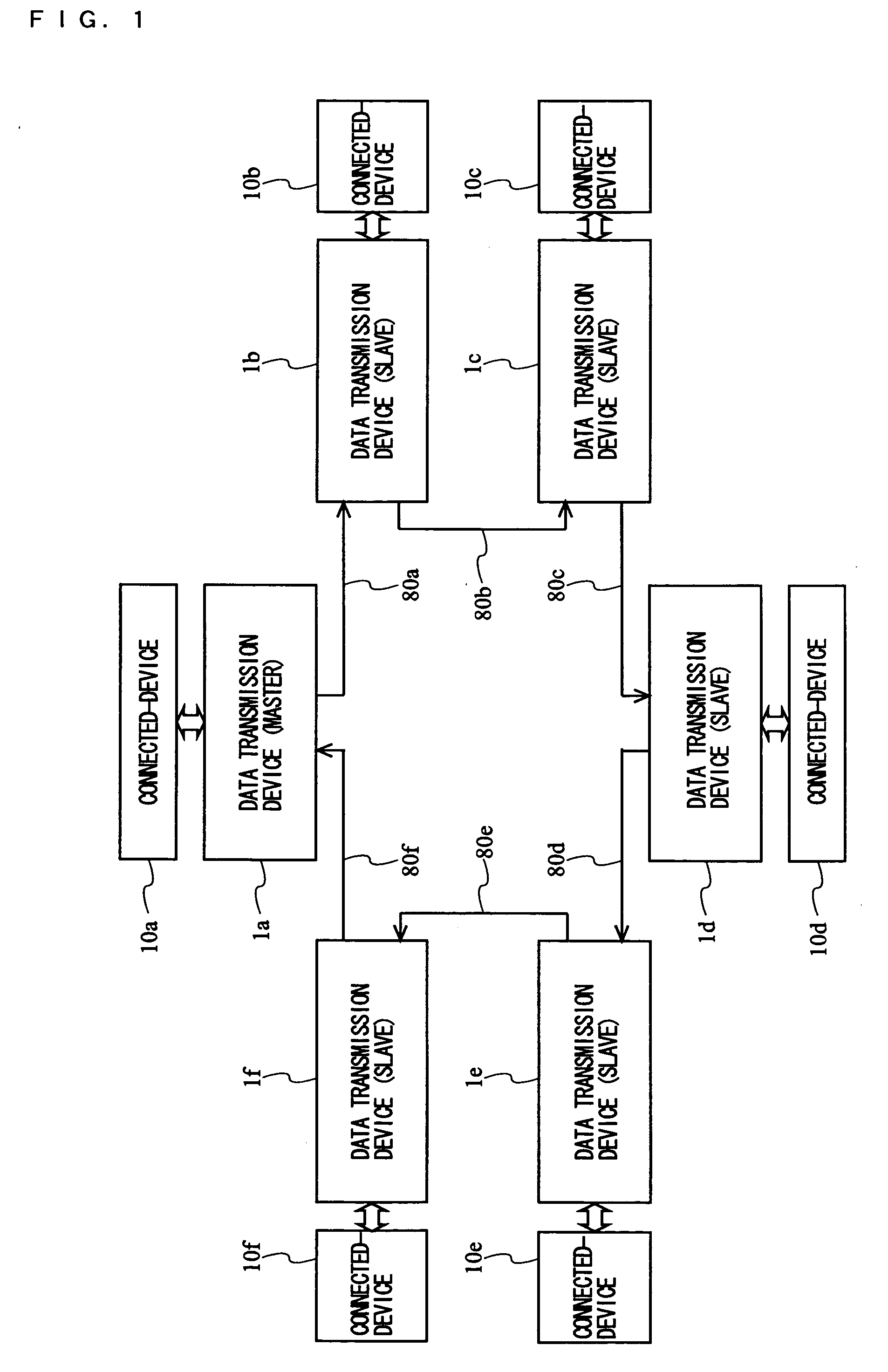
[0061] With reference to FIG. 1, a data transmission system according to a first embodiment of the present invention is described. FIG. 1 is a block diagram illustrating a configuration of the data transmission system.

[0062] In FIG. 1, the data transmission system according to the first embodiment has a ring topology as its physical topology in which a plurality of nodes are connected according to the ring topology, thereby forming a unidirectional ring LAN. An example of such a data transmission system is described below where the nodes are composed of six data transmission devices 1a to 1f, which are connected via transmission lines 80a to 80f so as to form a ring structure, and transmitted data is transmitted via the transmission lines 80a to 80f in a single direction. To the data transmission devices 1a to 1f are connected connected-devices (e.g., audio devices, navigation devices, or information terminal devices) 10a to 10f each conducting a process based on data transmitted t...

second embodiment

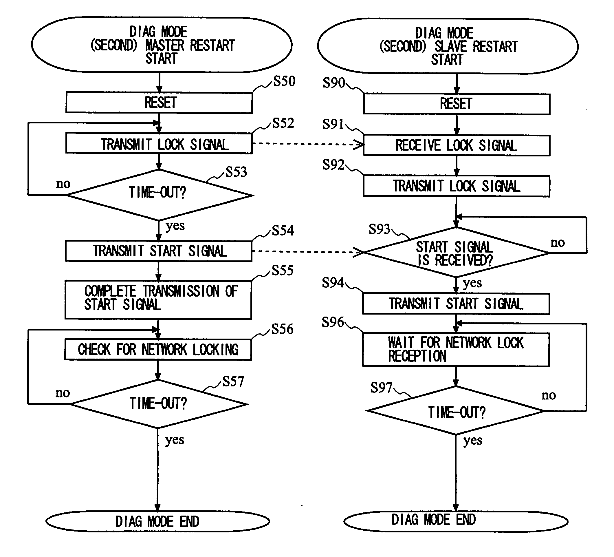
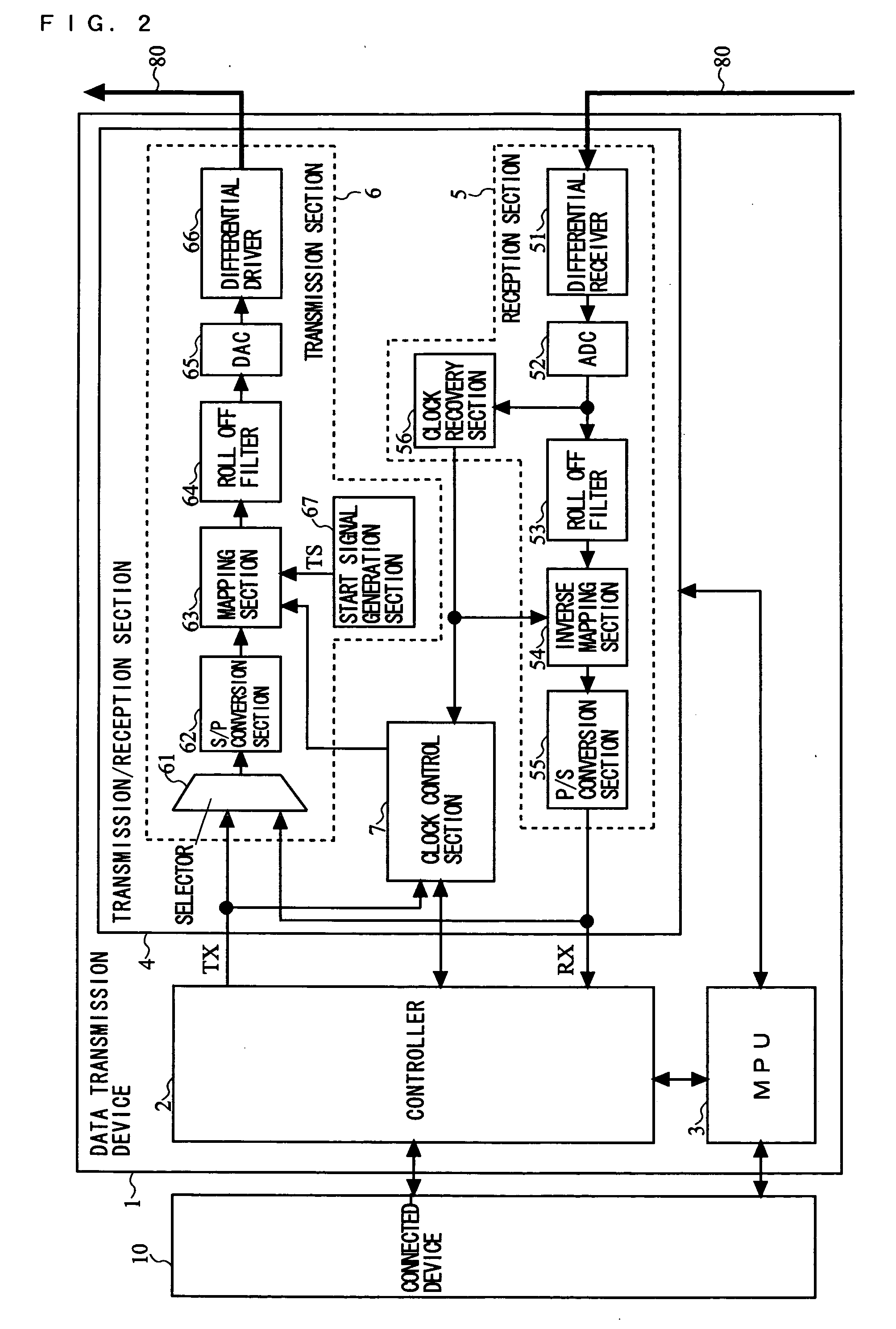
[0120] Next, a data transmission system according to a second embodiment of the present invention is described. The present data transmission system is different from the above-described first embodiment in the procedure of the initialization process. Specifically, although the first embodiment prescribes a procedure in which the physical layer and data link layer of the data transmission system are initialized at the same time, in the second embodiment, the initialization process is performed according to a procedure in which the initialization for the physical layer of the data transmission system is completed first and thereafter the initialization for the data link layer is started. The structure of the data transmission system and the structures of a plurality of data transmission devices included in the data transmission system according to the second embodiment are identical to those of the first embodiment, which have been described with reference to FIG. 1 and FIG. 2. There...


PUM


Abstract

In the case where transmission and reception is made impossible at a certain portion, a data transmission system configured in a ring LAN performs an initialization process for a physical layer (a transmission / reception section 4) repeatedly, thereby setting as a master a data transmission device which is located most upstream in electrical communication from a disconnection point. With that data transmission device being the master, an initial setting of the physical layer such as a clock synchronization with another data transmission device or the like is established, and an initialization process for a data link layer is performed, whereby subsequent data transmission and reception is enabled. That is, the data transmission system configured in a ring LAN is able to perform communication using transmission lines excluding a damaged point even in the case where transmission and reception is made impossible at a certain portion.

Description

TECHNICAL FIELD [0001] The present invention relates to a data transmission system, a data transmission device, and a method therefor, and, more specifically, to a data transmission system, a data transmission device, and a method therefor for performing unidirectional electric communication between data transmission devices after establishing synchronization therebetween, the data transmission devices being connected with one another so as to form a ring structure via transmission lines. BACKGROUND ART [0002] In recent years, in car navigation or when doing the Internet, e.g., ITS (Intelligent Transport Systems), or when transmitting image information in space such as the inside of a motor vehicle, high-volume and high-speed communication is required. A great deal of study is being made on communication systems for transmitting such digitized video or audio data, or digital data such as computer data or the like. Also, introduction of a network for transmitting digital data into ev...

Claims


Application Information

Patent Timeline
IPC IPC(8): H04J3/06H04L12/437
CPCH04L12/437
Inventor AKITA, TAKASHIKATTA, NOBORUYASUI, NOBUHIKOSAKAI, TAKAHISAMIZUGUCHI, YUJITAKAHIRA, YUTAKAKAWADA, HIROTSUGUUMEI, TOSHITOMO
Owner PANASONIC CORP
Learn More