Endoprosthesis for a metatarsophalangeal joint

Inactive Publication Date: 2006-04-06
SMITH & NEPHEW ORTHOPAEDICS
View PDF22 Cites 99 Cited by
  • Summary
  • Abstract
  • Description
  • Claims
  • Application Information

AI Technical Summary

Benefits of technology

[0009] One aspect of the invention is the realization that it should be possible, by means of a centered alignment of the metatarsal to the proximal phalanx or vice-versa, to reduce the risk of dislocation. Another aspect of the invention is the realization that the endoprosthesis sho

Problems solved by technology

However, it is intraoperatively very difficult to center the implant in the bone.
For example, the joint insert can form an overhang, which results in irritation of soft tissue

Method used


Image

  • Endoprosthesis for a metatarsophalangeal joint
  • Endoprosthesis for a metatarsophalangeal joint

Examples


Embodiment Construction

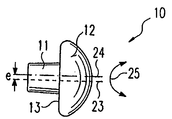
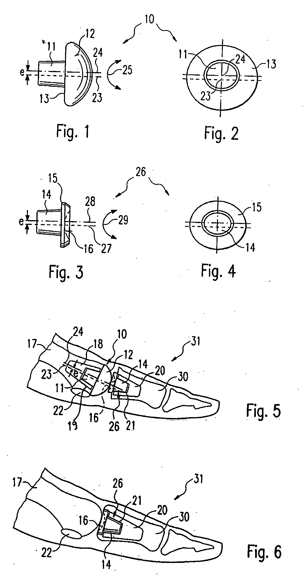
[0022]FIGS. 1 and 2 show one embodiment of a proximal joint insert or proximal prosthesis-half 10. In the illustrated embodiment, the proximal prosthesis-half 10 comprises a convex prosthetic sliding surface 12 with an anchoring pin 11 of conical shape, which is arranged eccentrically with respect to a central axis 23 of the sliding surface 12. However, one of ordinary skill in the art will recognize that the prosthetic sliding surface 12 can have other shapes, such as concave. Likewise, the anchoring pin 11 can have other suitable shapes, such as cylindrical. The proximal prosthesis-half 10 also defines a rear side or surface 13, which is located opposite the prosthetic sliding surface 12. Reference numeral 24 denotes a central axis of the anchoring pin 11. In the illustrated embodiment, the central axes 23, 24 are offset from one another by a predetermined eccentricity “e”. In one preferred embodiment, the eccentricity “e” is between about 0.5 mm and about 5.0 mm. In another prefe...


PUM


Abstract

An endoprosthesis for a metatarsophalangeal (MTP) joint, especially a basal joint of a large toe, a toe joint or a finger joint, has a prosthesis-half defining a concave or convex prosthetic sliding surface, and means arranged eccentrically with respect to the prosthetic sliding surface of the prosthesis-half for anchoring the latter in the bone.

Description

CROSS-REFERENCE TO RELATED APPLICATIONS [0001] This application claims priority to German Patent Application No. DE 102004043700.9, filed Sep. 9, 2004, the entire contents of which are hereby incorporated by reference and should be considered a part of this specification. BACKGROUND OF THE INVENTION [0002] 1. Field of the Invention [0003] The invention relates to an endoprosthesis for a joint, and in particular to an endoprosthesis for a metatarsophalangeal (MTP) joint, especially a basal joint of a large toe, a toe joint or a finger joint, having a prosthesis-half defining a concave or convex prosthetic sliding surface. [0004] 2. Description of the Related Art [0005] A prosthesis for an MTP joint is described, for example, in EP 0 827 386 B1. In addition thereto, it should be stated that the joint replacement for a basal joint of a toe, especially a large toe, nowadays consists of replacing the joint surface either distally (proximal phalanx) by a prosthesis-half or hemiprosthesis ...

Claims


Application Information

Patent Timeline
IPC IPC(8): A61F2/42
CPCA61F2/4225
Inventor FREY, THEO
Owner SMITH & NEPHEW ORTHOPAEDICS
Why Eureka
Try Eureka